Categories: Practical Electronics, Novice electricians, Electrician at home, Sockets and switches
Number of views: 2016012
Comments on the article: 60

Feedthrough switch. Wiring diagram
 

Feedthrough switch. Wiring diagramCircuit-breaker circuits allow turning on and off the lighting from two or more different places of their installation. In some cases, this is not only convenient, but also very necessary.

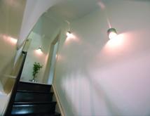
For example, the room has a long corridor. It is naturally lit. Turning on the light at the beginning, and having this circuit breaker connection diagram, you don’t have to come back again to turn off, but you can do it with the second switch that is installed at the other end of the corridor. Very often, such schemes are also used to control the lighting of stairs.

Which is better to use: loop-through switches or bistable relays? Answer here.


How to connect pass-through switches for independent control of lighting from two places.

Let's take a closer look at this wiring diagram consisting of two loop-through switches. It will require two switches (they are also called “pass-through”), each of which has three contacts and two switching positions. Moreover, the switching mode must be of "cross over nature", that is - one contact is common to the other two. In one position it is closed with one of them, and in another position, naturally, with another. Consequently, the general isolation of all three contacts is completely excluded.

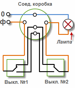
Connection diagram of a passage switch for controlling a lamp from 2 places
Connection diagram of a passage switch for controlling a lamp from 2 places

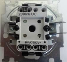
Feedthrough switch

Three-way and two-way switch through passage (on top is a common contact)


Explanations for the schemes

Now let's figure out the drawn diagrams. Both schemes consist of junction box, passage switches themselves, a lamp and connecting wires (during installation, these will be two, three and four-core cables). The first diagram shows wiring diagram for the through switch with control from two different places.

As you can see, one wire (in our case it is zero) goes from the power source to the junction box and from it to the lamp. Another (phase wire), after the box is connected to the common contact of one of the switches. Two switched contacts of one switch are connected to two contacts of the second switch (through the box). Well, with the common contact of the second switch, the phase is fed to the second contact of the lamp.

As for the installation of this scheme itself: they are put in their installation places breakersfrom which three-core cables are output. Lamps are mounted that will be connected in parallel and from which as a result a two-core cable comes out.

Further, a junction box is installed in the most suitable place (taking into account the minimum cable length and a convenient location for the location of this box). The cable from the fixtures, the power supply and the passage switches themselves is introduced into it. This box is made wire connection among themselves, as shown in the diagram.

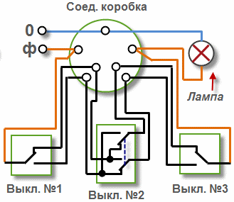
Connection diagram of a through switch for controlling a lamp from 3 places

Connection diagram of a through switch for controlling a lamp from 3 places

How to control lighting from three places


Three-place control circuit breaker connection diagram not much different from the previous one (the general principle of operation is the same). It added another pass-through switch, which is slightly different from the previous ones. As can be seen from the diagram, this twin switch. That is, when one key is pressed, the two contacts are simultaneously thrown over electrically independent of each other. In addition, as you should have noticed, a four-wire cable comes out of it.

The connection diagrams of through-passage switches of this type are good in that they are relatively simple in their design (no additional components are required). But they are limited by the number of such control places.

The task of independent lighting control from two places can also be solved using special impulse relays and blocks for remote lighting control.

Other ways to implement lighting control from two or more places:

Lighting Control Schemes

Schematic and wiring diagrams of lighting in an apartment and a house

See also:

Design and principle of operation of switches and switches of various kinds

Selected articles on the topic "Lighting control in the house"

See also at bgv.electricianexp.com:

  • Lighting control from two, three or more places
  • Which is better to use: loop-through switches or bistable relays
  • How to automatically control staircase lighting
  • Lighting control in the house
  • Wiring diagrams in an apartment and a house - the best articles

  •  
     
    Comments:

    # 1 wrote: | [quote]


    It would be nice to mention that the three-pole loop-through switch and the four-pole switch have their own well-established names, and not "slightly different ... paired."

     
    Comments:

    # 2 wrote: Alexei | [quote]


    Guys tell me what the dashed line on the connection diagram of the switch of 3 places means?

     
    Comments:

    # 3 wrote: andy78 | [quote]


    This is a mechanical connection between the contacts (paired switch).

     
    Comments:

    # 4 wrote: | [quote]


    Thank you for the correct connection scheme gangers. Helped a lot.

     
    Comments:

    # 5 wrote: Sergei | [quote]


    Zero switching is fraught with electric shock, the phase must be switched.

     
    Comments:

    # 6 wrote: | [quote]


    Places of passage switches are not limited, at least 100 medium ones can be supplied.

     
    Comments:

    # 7 wrote: | [quote]


    2 Segrey:

    Duck here phase and commute ...

     
    Comments:

    # 8 wrote: | [quote]


    An instructive and informative site for you! I wish you success in your development.

     
    Comments:

    # 9 wrote: | [quote]


    Thank you so much for your unique site.

     
    Comments:

    # 10 wrote: | [quote]


    I don’t know why the author wrote that the number of management places is limited. Personally, he turned off the lighting from seven positions. The number of "medium" switches can be unlimited. The only difficulty is in switching. And then, when rejecting each wire, during installation, it does not cause difficulties.

     
    Comments:

    # 11 wrote: | [quote]


    I could not find the answer to my question. abb circuit. two double pass switches. On the chandelier.

     
    Comments:

    # 12 wrote: Nikolay | [quote]


    For the first time in my life, I connected walk-through switches on my own. I used to replace conventional ones, but I did not have to deal with pass-through switches before. I connected them as shown in the diagrams in the article. Everything works! It's nice when you do something with your own hands and everything turns out the first time. Thanks for the information! Very good and helpful article!

     
    Comments:

    # 13 wrote: | [quote]


    Management from three places ... in general, I made myself this, the only thing is that if you turn on the light with a cross or as it is written here by a paired switch, and turn it off with one of the two passageways, then do not turn on the cross again. It is necessary to turn on the light again with one of the two passageways, and turn off the cross.

     
    Comments:

    # 14 wrote: | [quote]


    Comment No. 13 is somewhat incorrect. The cross switch is connected between two walk-throughs, its purpose is the mutual reconnection of two lines highlighted in black (see diagram). He does not impose any restrictions on lighting control. The cross switch is not paired, sometimes called: the deviator.

     
    Comments:

    # 15 wrote: | [quote]


    The husband himself connected the passage switches in the corridor. One turns on - the other turns off. If someone enters the street, then he cannot turn it on first. So it should be? or something is not correctly connected?

     
    Comments:

    # 16 wrote: | [quote]


    But is it not more profitable to make a circuit through a magnetic starter?)

     
    Comments:

    # 17 wrote: Alexei | [quote]


    Comment No. 15. Incorrectly attached.Each can be turned on and off regardless of the position of the other. The same applies when using intermediate (medium) switches.

     
    Comments:

    # 18 wrote: | [quote]


    The electrician installed two passage switches. The one in the hallway broke twice and knocked out the machine, after about 7-8 switches. Once changed to a new one. The second time he dismantled it, he saw that the contacts were welded. I cleaned, collected, after 7-8 clicks it broke again. Apparently the arc slips, and both when the light is turned off, and when it is turned on. What could it be? How to fix? With the second until this happened, they used little.

     
    Comments:

    # 19 wrote: Artemy | [quote]


    BorisYou may have damaged wire insulation in the circuit breaker. I advise you to check and completely isolate them.

     
    Comments:

    # 20 wrote: | [quote]


    Quote: Boris
    # 18 wrote: Boris | [quote]

    Most likely you have too powerful lamps, and the switches are not designed for such a load. When switching, an arc arises, which breaks your switches.

    If more than 3 switches or a load of more than 2.2 kW (10A) is cheaper and easier to put buttons and relays. For instance:
    Switching relays Legrand comply with EN / IEC 6066922. No more than two auxiliary contacts are installed on one pulse relay
    Single pole, 16 A, 250 V ~
    voltage type circuit Width
    contact control modules
    1 041 60 12 in 1 n.a. 1
    1 041 61 24 in 1 n.a. 1
    10 041 63 230 in 1 n.a. 1
    Bipolar, 16 A, 250 V ~
    1 041 65 24 in 2 n.a. 1
    1 041 66 48 in 2 N.O. 1
    1 041 67 230 in 2 N.O. 1
    Quadruple, 16 A, 400 V ~
    can be used in three-phase circuits
    1 041 71 230 in 4 N.O. 2

     
    Comments:

    # 21 wrote: | [quote]


    PLEASE TELL ME. I SAY THAT FOR THROUGH CIRCUIT BREAKERS CAN GO

    ABB BJB Basic 55 Bel Switch 1-button, NO contact BO 2026 UC-94 ONLY NEED WIRING THROUGH BRUSHES AND THERE TO INSTALL ANY RELAY. I HAVE NOT FOUND ANYWHERE. HELP PLEASE IF ANYONE KNOWS ABOUT THIS SOMETHING.