Categories: Featured Articles » Practical Electronics
Number of views: 23693
Comments on the article: 0
How to check the chip for performance
Before checking any chip for performance, you need to know and understand its device, at least approximately. This is necessary in order to pre-imagine what signals or voltages to expect from a working microcircuit at its terminals.
Best for checking specific microcircuits to assemble a circuit for testing it at least on a breadboard — this is if the chip is new or already soldered.
In general, if the device of the microcircuit is known, then in some situations it can be checked without even soldering from the board on which it is installed, simply by measuring the signals on the legs with a multimeter or an oscilloscope. Then the presence or absence of a signal or a distorted pulse shape will immediately show what is what.

External inspection of the chip
Suppose that the microcircuit is still installed on the board and it is undesirable to immediately evaporate it. Before applying power to the board, carefully inspect the chip from all sides. Perhaps there are obvious physical signs of its malfunction: a crack on the case, a burned out or dropped output, a short circuit between the legs due to a piece of wire (and this happens), burned body components, etc. If no damage was found during inspection, can go further.
If the board is powered up to the current moment, then you can carefully (with safety precautions!) Proceed to further check the microcircuit.
Power Lead Check
First of all, they diagnose the power circuits of the microcircuit. This can be done with a voltmeter (multimeter). It is very easy to clarify the power conclusions of a well-known microcircuit - just look at the documentation (datasheet) on it. Plus, positive power is designated in the datasheet as VCC +, negative power is VCC-, the common wire is GND.
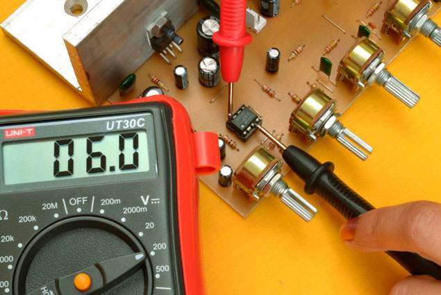
So, the negative probe of the multimeter is installed on the common wire - it rests on the negative output of the microcircuit, and the plus (red) probe of the multimeter - on the corresponding power leg. If the voltage corresponds to the norm for the microcircuit, then the power is supplied as it should, therefore the power circuits of the entire device are working.
If the power supply voltage is not normal, then it is necessary to further check the power supply circuit itself, at least by preliminary unsoldering it from the microcircuit. If the power circuits work fine without a microcircuit, the problem in the microcircuit will be taken into account, and in the worst case it really has to be changed. If the problem is in the power circuits, then it is most likely necessary to repair them (capacitor, stabilizer, etc.).

Testing the voltage reference
Next, check all known conclusions of the chip. For example, you can start by measuring the voltage at the output of the Vref reference voltage source integrated into the microcircuit, the normal value of which is indicated in the documentation. At this pin there should be a constant voltage of a certain value relative to the common wire. If it is smaller or much larger, something is wrong inside the microcircuit or in the body parts, and the diagnosis should be continued.
Checking timing chains
If there is any RC circuit on the chip, then, as a rule, sawtooth vibrations should be observed on it, as a rule. At this stage, it will again be useful to turn to the datasheet to understand where this circuit is located, if it is provided, and on which leg there should be vibrations.
Verification is carried out by an oscilloscope. Its common probe clings to the minus power, and the measuring one - to the corresponding output of the microcircuit. If there are fluctuations and their shape is acceptable - everything is in order, you can go further. If there is no hesitation, then most likely the problem is in the microcircuit or in the weighted timing components.
Testing Signal Pins
Finally, check the signal outputs (outputs) of the chip. If the chip controls some key or the next block in the circuit, then the correct signals must be present at the corresponding outputs (or at least at one output, if it is the only one) of the chip. Look in a datasheet to what conclusions the operated chains should approach.
Test the findings with the oscilloscope in the same way as you tested the RC circuit. If the signal is normal and not significantly distorted compared to the normal form, then everything is in order. If the signal is absent or severely distorted, most likely the microcircuit is damaged, and it should be replaced by checking the controlled circuit first, because in reality it can cause the microcircuit to fail.
See also at i.electricianexp.com
:
