Categories: Featured Articles » Practical Electronics
Number of views: 8742
Comments on the article: 0
IGBT transistors - the main components of modern power electronics
An IGBT transistor (short for English Insulated-gate bipolar transistor) or an insulated gate bipolar transistor (abbreviated IGBT) is a three-terminal semiconductor device that combines a power bipolar transistor and a field-effect transistor controlling it inside one housing.
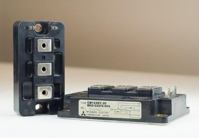
IGBT transistors are today the main components of power electronics (powerful inverters, switching power supplies, frequency converters, etc.), where they serve as powerful electronic switches that switch currents at frequencies measured in tens and hundreds of kilohertz. Transistors of this type are produced both in the form of separate components, and in the form of specialized power modules (assemblies) for controlling three-phase circuits.

The fact that the IGBT transistor includes transistors of two types at once (cascaded) allows you to combine the advantages of two technologies inside one semiconductor device.
A bipolar transistor as a power transistor allows you to get a larger operating voltage, while the channel resistance in the open state is proportional to the current in the first degree, and not to the square of the current as conventional field effect transistors. And the fact that it is a field-effect transistor that is used as a control transistor minimizes power consumption for key control.
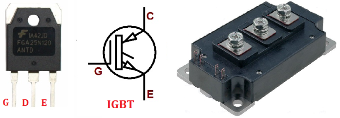
The names of the electrodes characterize the structure of the IGBT transistor: the control electrode is called the gate (like a field-effect transistor), and the electrodes of the power channel are called the collector and emitter (like a bipolar transistor).
A bit of history
Historically, bipolar transistors have been used on an equal footing. with thyristors as power electronic keys until the 90s. But the disadvantages of bipolar transistors were always obvious: a large base current, slow shutdown and overheating of the crystal, a strong temperature dependence of the main parameters, and a limited collector-emitter saturation voltage.
The field effect transistors (MOS structures) that appeared later immediately changed the situation for the better: voltage control no longer requires such large currents, the parameters of the switch are weakly dependent on temperature, the operating voltage of the transistor is not limited from below, the low resistance of the power channel in the open state extends the range of operating currents, the switching frequency can easily reach hundreds of kilohertz, in addition, the ability of field-effect transistors to withstand strong dynamic loads at high operating voltages is noteworthy.
Since the control of a field effect transistor is much simpler and more powerful than a bipolar one, there is a restrictive one inside. diode, - field-effect transistors immediately gained popularity in high-frequency switching voltage converters, as well as in Class D acoustic amplifiers.

Vladimir Dyakonov
The first power field effect transistor was developed by Viktor Bachurin back in the Soviet Union in 1973, after which it was investigated under the supervision of scientist Vladimir Dyakonov. Investigations of the Dyakonov group regarding the key properties of a power field-effect transistor led to the development in 1977 of a composite transistor switch, inside which a bipolar transistor was controlled by a field-effect insulated gate.
Scientists have shown the effectiveness of this approach, when the current properties of the power part are determined by a bipolar transistor, and the control parameters are determined by the field one. Moreover, the saturation of the bipolar transistor is eliminated, which means that the delay when turned off is reduced. This is an important advantage of any power key.
Soviet scientists obtained the copyright certificate No. 757051 "Pobistor" for a new type of semiconductor device. This was the first structure containing a powerful bipolar transistor in one housing, on top of which was a control field-effect transistor with an insulated gate.
")
As for industrial implementation, already in 1983 Intarnational Rectifier patented the first IGBT transistor. And two years later, an IGBT transistor with a flat structure and a higher operating voltage was developed. This was done simultaneously in the laboratories of two companies - General Electric and RCA.
The first versions of insulated-gate bipolar transistors had one major drawback - slow switching. The name IGBT was adopted in the 90s, when the second and third generation of IGBT transistors were created. Then these shortcomings were gone.
Distinctive Benefits of IGBTs
Compared to conventional field effect transistors, IGBTs have higher input impedance and lower power that is spent on gate control.
Unlike bipolar transistors, there is a lower residual voltage when on. Losses in the open state, even at high operating voltages and currents, are quite small. In this case, the conductivity is like that of a bipolar transistor, and the key is controlled by voltage.
The range of operating voltage collector-emitter for most widely available models varies from tens of volts to 1200 or more volts, while currents can reach up to 1000 or more amperes. There are assemblies for hundreds and thousands of volts in voltage and currents of hundreds of amperes.
It is believed that field-effect transistors are better suited for operating voltages up to 500 volts, and IGBT transistors are suitable for voltages greater than 500 volts and currents greater than 10 amperes, since lower channel resistance in the open state is extremely important at lower voltages.
IGBT Transistors
The main application of IGBT transistors is found in inverters, switching voltage converters and frequency converters (for example, the half-bridge module SKM 300GB063D, 400A, 600V) - where there is high voltage and significant power.
Welding inverters - a separate important area of application of IGBT transistors: high current, power more than 5 kW and frequencies up to 50 kHz (IRG4PC50UD - classic of the genre, 27A, 600V, up to 40 kHz).

You can not do without IGBT on urban electric transport: with thyristors, traction motors show lower efficiency than with IGBT, moreover, IGBT achieves a smoother ride and a good combination with regenerative braking systems even at high speeds.
There is nothing better than IGBT when you need to switch at high voltages (more than 1000 V) or control a variable frequency drive (frequencies up to 20 kHz).

On some circuits, IGBT and MOSFET transistors are completely interchangeable, since their pinout is similar, and the control principles are identical. The gates in this and in the other case represent a capacity of up to nanofarads, with a charge-holding recharge on which the driver installed on any such circuit can easily handle and provides adequate control.
See also:Power MOSFET and IGBT transistors, differences and features of their application
See also at electro-en.tomathouse.com:
