Categories: Featured Articles » Practical Electronics
Number of views: 17628
Comments on the article: 0
How to check a field effect transistor
To check the health field effect transistor You can use any digital multimeter with the function of "diode ringing". This function works in such a way that allows you to measure the direct voltage drop at the p-n junction, which will be displayed on the display of the multimeter during testing.
In the process of this test, the multimeter is able to pass current through the circuit under test within a few milliamps, and if the voltage drop turns out to be too small, then if the device has a sound alert function, it will clear. And since p-n junctions are present in any field-effect transistor, we can expect a completely adequate result.
Before checking the field effect transistor for continuity, short-circuit with a foil all its terminals for a second to remove static charge in order to discharge all its transitional capacities, including the gate-source capacitance.

Checking the built-in reverse diode
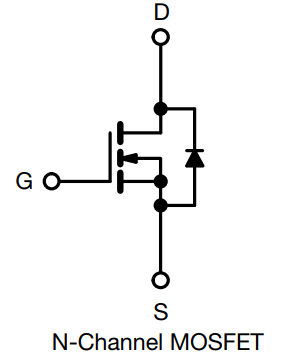
In almost any modern field-effect transistor, with the exception of their special types, an internal “protective" circuit is connected parallel to the drain-source circuit diode.
The presence of this diode inside the field is due to the features of the technology for the production of powerful transistors. Sometimes it interferes, it is considered parasitic, but in most field-effect transistors without it, as part of the integral structure of the electronic component, you can not do. Therefore, in a working field-effect transistor, this diode must also be working. In the n-channel field effect transistor, this diode is connected by the cathode to the drain, the anode to the source, and in the p-channel by the anode to the drain, and the cathode to the source.
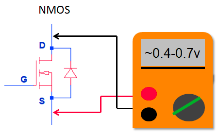
Turn on the multimeter in the “ringing” mode of the diodes. If the field-effect transistor is n-channel, then attach the red probe of the multimeter to its source (source), and the black to the drain (drain).
Usually the drain is in the middle and connected to the conductive substrate of the transistor, and the source is the right terminal (check this in the datasheet). If the internal diode is working, the multimeter will display a direct voltage drop on it - in the region of 0.4-0.7 volts. If now the position of the probes is reversed, the device will show infinity. If so, then the internal diode is working.
Check drain-source circuit
The field effect transistor is controlled by the electric field of the gate. And if the gate-source capacitance is charged, then the conductivity in the drain-source direction will increase.
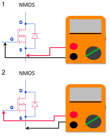
So, if the transistor is n-channel, attach the black probe to the gate and the red to the source, and after a second, change the position of the probes to the opposite — red to the gate and black to the source. So at first we probably unloaded the shutter, and after that we charged it. The shutter is usually on the left, and the source is on the right (see datasheet).
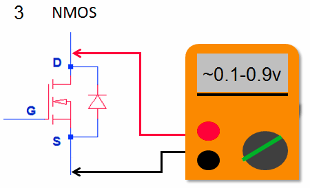
Now move the red probe from the shutter to the drain, and let the black one remain at the source. If the transistor is working, then as soon as you move the red probe from the gate to the drain, the multimeter will show that there is a voltage drop on the drain (not infinite, but may increase) - this means that the transistor has switched to a conducting state.
Now the red probe is at the source, and the black probe is at the gate (we discharge the shutter with the opposite polarity), after which the red probe is at the drain again, and the black probe at the source. The device should show infinity - the transistor is closed. For a p-channel field effect transistor, the probes simply swap.
If the appliance protects
If the device protects the drain-source at the verification stage, this can be quite normal, because in modern field-effect transistors, the drain-source resistance in the open state is very small. The main thing is that there should be no shutter-source ring and drain-source, especially at that moment when the shutter is charged with opposite polarity.Alternatively, you can connect the gate to the source and in this position call the drain-source (for the n-channel red to drain, black to the source), the device should show infinity.
See also at bgv.electricianexp.com
:
