Categories: Featured Articles » Practical Electronics
Number of views: 37848
Comments on the article: 0
Electronic Circuit Troubleshooting Methods
Most often, people are interested in electronics in order to be able to repair a device. Only a small part of lovers are engaged in self-development. Although theoretical knowledge provides a general understanding of how the components work, it’s much more important to know how to test them for repairs. We will tell you how to find a malfunction in an electronic circuit with your own hands, eyes and a simple tool.
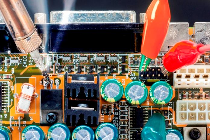
Basic troubleshooting
Before carrying out repairs it is important to determine what the problem is - this process is called diagnostics. So, we can distinguish two stages of testing electronic devices:
1. Checking the performance of the device. It does not always happen that the device is completely “dead”, you need to check if the device does not turn on at all, or turns on and off immediately, or some specific buttons or functions do not work.
For example, when repairing LCD monitors, there is such a problem as a backlight failure. At the same time, the monitor may either not turn on at all then its indicator blinks, or the indicator indicates the on state, but there is no image. In this case, if you shine a flashlight on the screen, you can see that the image is still there and the monitor seems to be working, but it is dark - and this is just one example where a preliminary check simplifies diagnostics.
2. Visual inspection. Outwardly, most problems with an electrical appliance can be identified. It can be just burnt components - diodes, resistors, transistors and capacitors, as well as soldering defects or mechanical damage to the elements and the printed circuit board itself.
3. Measurements. If the board and parts look normal, then go to the measurements. They are carried out mainly using a multimeter and an oscilloscope. In some cases, specialized devices are used, such as frequency meters, logic analyzers, and more.
So, a generalized troubleshooting algorithm is:
-
Inspection board;
-
Determination of excessive heating of the electronic components of the board;
-
Measurement and dial multimeter;
-
Using an oscilloscope and other instruments;
-
Replacing a failed part or block.
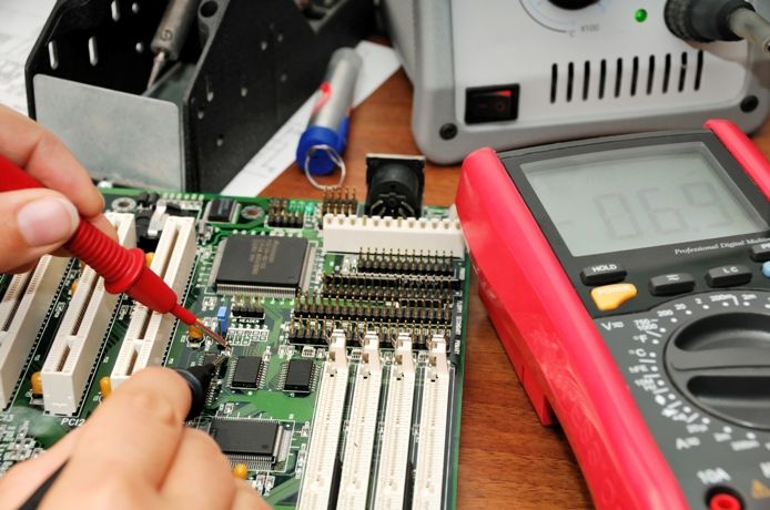
Visual inspection
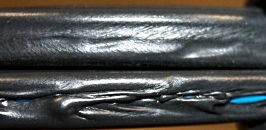
Visual inspection should be carried out from general to particular. Or in simple words - to examine the general view of the electronic device, we immediately check the integrity of the cables and power wires. Their cover should be even and whole, without kinks and sharp bends, cones and other irregularities on the shell should not be.
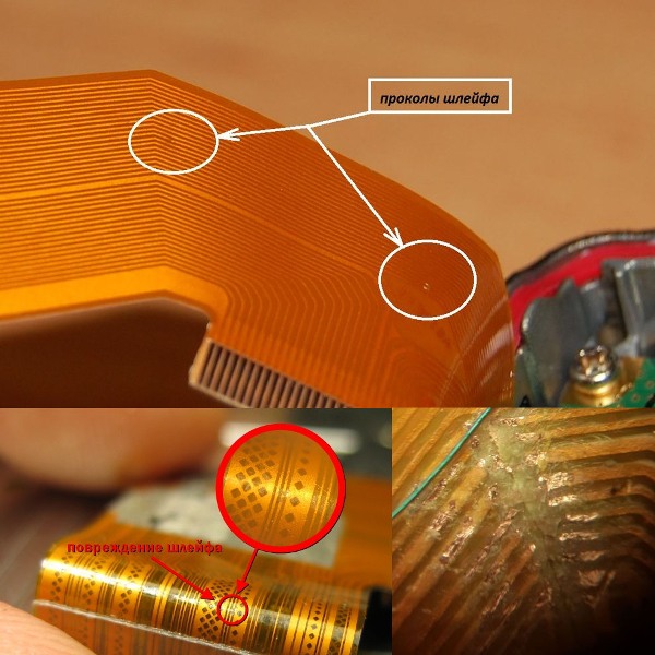
After you have verified the integrity of the device, you need to disassemble it and get to the printed circuit board. Inspection of the insides should begin with checking the integrity of the loops, wires of other interconnects. It is important not to tear them even when disassembling, since often the cables go from the boards to the key blocks and displays attached to the case.
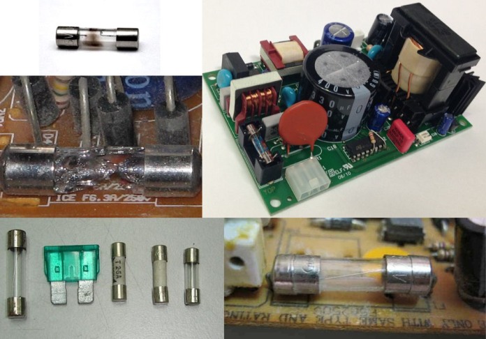
Next, check the integrity of the fuse in the power circuit, often if it is blown, you can determine with the naked eye. It stands near the place where the power cord is connected to the board.
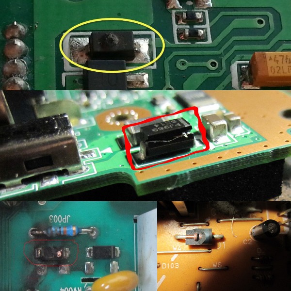
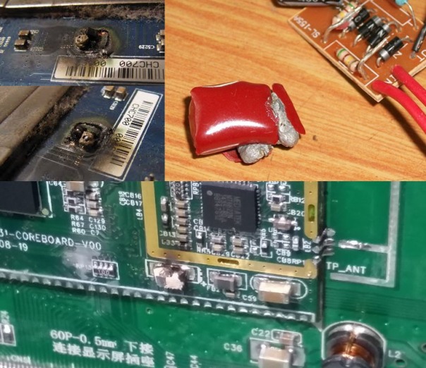
After that, inspect for signs of heating or soot on the board and damaged components. Consider how faulty electronic components look. For example, the case of faulty transistors and burnt diodes breaks or they crack.
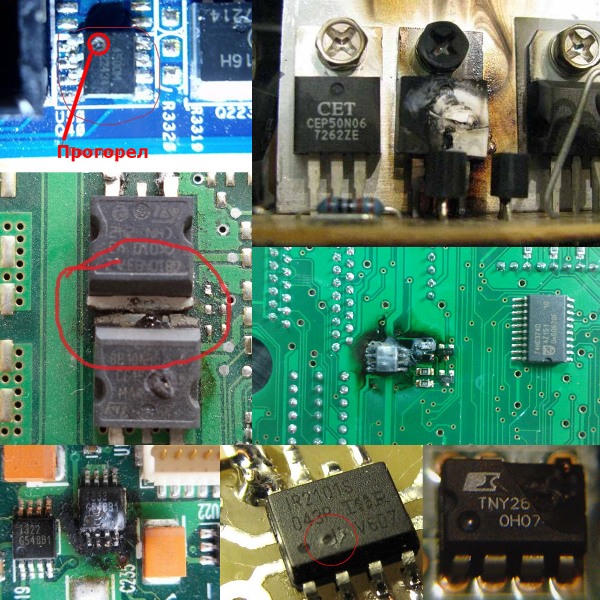
A crack or small dot appears on the integrated circuits. In some cases, both burn out, leaving traces of burning on the board. Pay attention to whether there is a characteristic smell of burning insulation. So it is possible to localize from which element or part of the board this smell emanates. How to identify burnt transistors and microcircuits you see below.
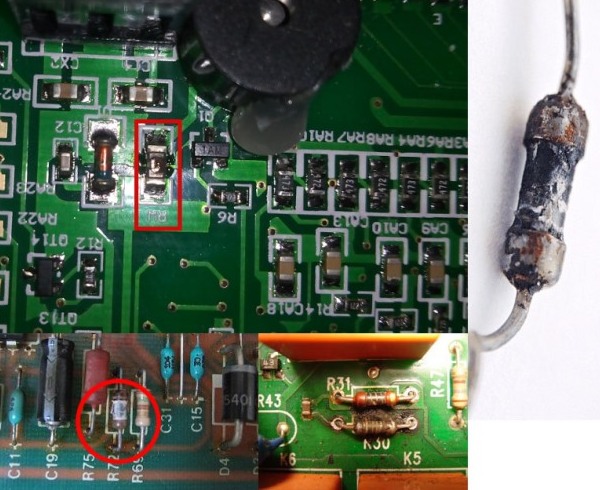
Resistors usually burn out or darken, less often the resistive layer breaks and the part looks good.
How to identify burnt capacitors? They basically pierce "short" between the plates and, if they are in the power circuit, then the board tracks or the capacitor case are damaged. If the circuit was low-current, a punched capacitor will simply short-circuit it without visible traces of the flow of large currents. Capacitor housings crack less often.
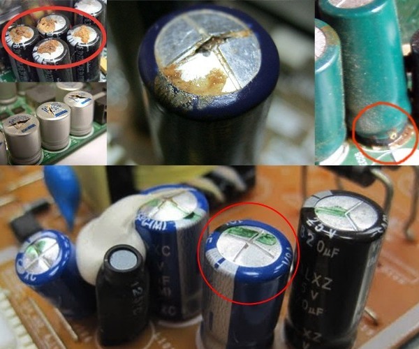
While electrolytic capacitors can be calculated from a deformed housing cover or traces of an electrolyte leaking down. There are two diagonal grooves on the capacitor cover, it is needed so that the case does not break in an emergency. In this case, the lid swells or cracks. Slowly squeezes the bottom.
With SMD components, the situation is somewhat more complicated. Often they are extremely difficult to consider for integrity. There is one method for finding a short circuit in a board with SMD - this is thermal paper, such paper is used in a cash register, so you can use any check. Printing on it is due to heating. This means that when you apply power to the board, a short-punched part will overheat and print on paper. You can see the troubleshooting method using thermal paper in the video:
But you need to remember electrical safety and not resort to such a diagnostic method if you are not sure if there is a dangerous voltage. This can be done safely and accurately. with a thermal imager.
To detect a short circuit in heating, in most cases you will need a laboratory power supply or other current-limited power supply. If you carry out diagnostics of 220V circuits, you can use the control lamp, if there is a short circuit, then the lamp will light up in full heat. In fact, it will act as a current-limiting resistor.
During a visual inspection, it is important to determine the state of the contacts of all detachable connections. They should be clean, free of oxides with a characteristic copper or silver sheen. If the contacts are not too oxidized, they can be cleaned with a stationery eraser or with the wooden side of the match.
In more advanced cases, they need to be tinned, so with tin you will restore the contact surface. The worst option is when there is nothing to clean or tin, then you need to either change the whole board, or solder conductors to the board tracks and connect them through them.
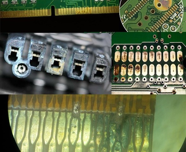
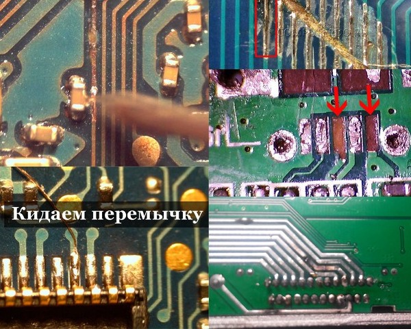
Also carefully inspect the circuit board tracks, they can burn out, crack when the board bends, peel off and oxidize. They are restored either with a drop of tin, or with a piece of wire when the tracks are too tight - they are replaced with a piece of wire - a thin winding wire or twisted pair lived, soldering them to the beginning and end of the printing track.
To summarize, find out 5 tips for external diagnostics of electronics:
1. Most of the faults can be found during an external examination;
2. Carefully check the quality of soldering and the presence of microcracks;
3. Pay particular attention to power circuits;
4. Swollen electrolytic capacitors in most cases are both the cause of complete inoperability and inoperability of some individual functions;
5. Not always outwardly operational part is such.
Measurement and circuit breaker
If the external examination does not bring results, then take a series of measurements. If the device does not show signs of life and:
-
His fuse has blown - then with a multimeter we ring the circuit and find in which section we have a short circuit. Call mode in most multimeters is combined with the diode test mode (in the figure below);
-
If the fuse is operational, we check with a voltmeter whether the supply voltage is coming to the board.
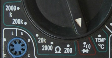
If the voltage does not come, then the problem is most likely in the cable, you can determine this by ringing the cable from the plug to the point of connection to the printed circuit board.
Important:
Do not plug the power supply directly into the network if you are not sure that you have fixed all the problems. Connect the incandescent bulb that we mentioned in the middle of the article in series.
The next step is to check the power circuit, for this we turn on the device and check the presence of the output voltages of the power supply. Please note that there are cases when the power supply does not turn on without load. Then we check the serviceability of the power supply, it starts with checking the diode bridge, we examined this process in detail in the article - How to check the diode bridge
After you have verified that the diode bridge is working, you should check whether voltage is coming. to PWM controller. If not, then look for an open circuit on the board, if it comes, then the procedure for checking it is depicted in the video below:
You should also check the power supply on the blocks. You can read about it. in the article on repairing power supplies for LED strips.
Further diagnostics of the electronic device board consists in step-by-step measurement of the parameters of each of the components and their comparison with the nominal values. The task is greatly simplified if you have a diagram of the device being repaired.
If you have an oscilloscope, the diagnosis will be greatly simplified, since checking the PWM signals at the output of the controller and at the bases or gates of transistors is normally only possible in this way. How to use the oscilloscope is described in the article. What can be done with an oscilloscope and a number of other articles of our site from the thematic section Practical Electronics.
Conclusion
Electronics repair is not only knowledge of the principle of operation of elements, but also intuition, experience and good luck. The main thing to remember when repairing safety measures is that you should not touch the power supply board if voltage is applied to it. Discharge the filter capacitors of the power supplies, as their terminals can be up to 300 volts. And also when diagnosing circuits with integrated circuits - it is better to immediately look for the technical documentation for them, it can be found at the request "datasheet name of the chip."
See also: Home appliance repair lessons on video
See also at bgv.electricianexp.com
:
