Categories: Featured Articles » Practical Electronics
Number of views: 4841
Comments on the article: 0
Simple RC circuit for rectangular pulse delay
During the development of a pulse converter controller, for example, to construct a circuit with resonance retention, it may be necessary to delay the edges of the pulses and the decay of the pulse sequence when a rectangular signal is applied from one block of the circuit to another.
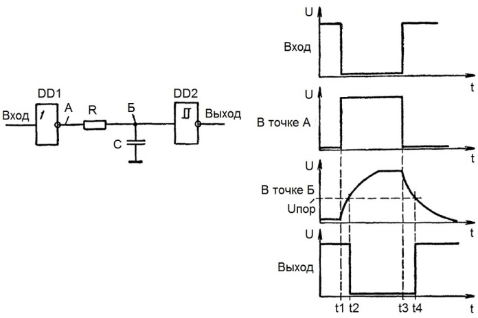
Sometimes a simple circuit consisting of two logical inverters and an RC circuit is suitable for solving this problem. For this purpose, it is convenient to use a microcircuit, which is a set of inverters with sufficiently defined thresholds. An example of such a microcircuit is 74N0404, there are 6 “NOT” logic elements in it, and it turns out that on one such microcircuit it is theoretically possible to construct 3 delay circuits according to the scheme below.

In practice, when the decay of a rectangular pulse arrives at the input of the first inverter, a leading edge arrives at the RC circuit from its output, and charging of the capacitor begins. The voltage across the capacitor increases exponentially, and theoretically reaches its maximum (Uп) after a period of time equal to 5 * RC seconds (here R is the resistor resistance in ohms, C is the capacitance in capacitors in farads).

If the capacitor is connected with its top plate to the input of the next logic element (to the input of the second inverter), then when the voltage on the capacitor reaches its threshold (Uпор), a drop will appear at its output, but with a corresponding time delay, relative to the drop applied to the input first inverter. Now, while the voltage on the capacitor has not dropped to the threshold of the second inverter, a low level voltage will be kept at its output.
When a leading edge of a rectangular pulse appears at the input of the first inverter, a drop will form at its output, that is, a low level voltage will appear, and the resistor will practically be connected to the zero bus. The capacitor will begin to discharge through the resistor.
The voltage across the capacitor will decrease exponentially, and theoretically reaches zero after a period of time equal to 5 * RC. But since the capacitor with its upper lining is connected to the input of the second inverter, as soon as the voltage on it drops to the threshold of its operation, a leading edge appears at its output, but with a corresponding time delay, relative to the front applied to the input of the first inverter. And now, until the voltage on the capacitor rises again to the threshold of the second inverter, a high level voltage will be kept at its output.

If the microcircuit is fed with a stabilized voltage of 5 volts, then the threshold voltages will always be at the same levels. And in practice, the time parameters of the delay achieved in this way can be calculated and adjusted as required using a variable resistor, especially if the developer has at hand oscilloscope.
The correct approach when selecting components of an RC circuit should be based on the fact that the duration of the phase-shifted pulse should preferably be more than 5 * RC, then the circuit will work accurately and the calculations using the above formulas will turn out to be correct.

If it is necessary to discharge the capacitor faster at the arrival of the next pulse, then a parallel branch from another resistor with a diode (or one diode, without a resistor at all) is added to the circuit, then for one of the cycles of working out the circuit, a different time constant will be obtained than for the second cycle.
In addition, it should be remembered that the input and output currents of the microcircuit (at the output of the first inverter, both during charging the capacitor and when it is discharged) are limited by the maximum permissible values that can be found in the datasheet for the used microcircuit.For this reason, capacitors with a capacity of not more than several nanofarads are used to construct phase-shifting circuits of such a plan, especially if a diode without a resistor is used in one of the branches of the RC circuit.
See also at bgv.electricianexp.com
:
