Categories: Featured Articles » Practical Electronics
Number of views: 23739
Comments on the article: 0
Resistor power: designation on the diagram, how to increase what to do if there is no suitable
In circuits of electronic equipment, one of the most common elements is resistor, his other name is resistance. It has a number of characteristics, among which there is power. In this article, we will talk about resistors, what to do if you do not have a suitable power element, and why they burn out.
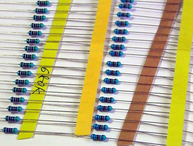
Resistor Characteristics
1. The main parameter of the resistor is the nominal resistance.
2. The second parameter by which it is selected is the maximum (or ultimate) power dissipation.
3. Temperature coefficient of resistance - describes how much resistance changes when its temperature changes by 1 degree Celsius.
4. Permissible deviation from the nominal value. Typically, the scatter of resistor parameters from one declared in the range of 5-10%, it depends on GOST or the technical specifications for which it is produced, there are exact resistors with a deviation of up to 1%, usually cost more.
5. The maximum operating voltage depends on the design of the element. In household electrical appliances with a supply voltage of 220V, almost any resistors can be used.
6. Noise characteristics.
7. Maximum ambient temperature. This is such a temperature that can be when reaching the maximum power dissipation of the resistor itself. We will talk about this in more detail later.
8. Moisture and heat resistance.
There are two more characteristics that beginners most often do not know about are:
1. Spurious inductance.
2. Spurious capacitance.
Both parameters depend on the type and design features of the resistor. Inductance has in any conductor, the question is in its magnitude. Typical values of parasitic inductances and capacitances are meaningless. Spurious components should be considered when designing and repairing high-frequency devices.
At low frequencies (for example, within the audio range up to 20 kHz), they do not make a significant impact on the operation of the circuit. In high-frequency devices, with operating frequencies of hundreds of thousands and above hertz, even the location of the tracks on the board and their shape make a significant impact.
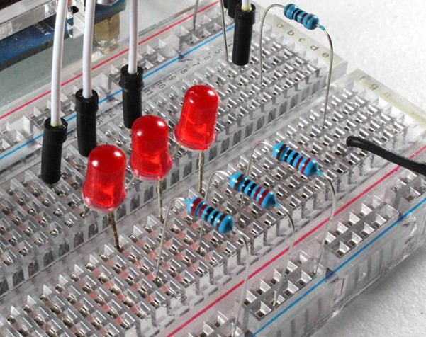
Power resistor
From the course of physics, many remember the formula for power for electricity, these are:P = U * I
It follows that it linearly depends on current and voltage. The current through the resistor depends on its resistance and the voltage applied to it, that is:
I = U / R
The voltage drop across the resistor (how much voltage remains on its terminals from the one applied to the circuit in which it is installed) also depends on the current and resistance:
I = U / R
Now we explain in simple words what the power of a resistor is and where it is allocated.
Any metal has its own specific resistance; this is such a value that depends on the structure of this metal itself. When charge carriers (in our case, electrons), under the influence of an electric current, flow through a conductor, they collide with the particles of which the metal consists.
As a result of these collisions, the flow of current is impeded. If very generalized, it turns out that the denser the metal structure, the more difficult it is for the current to flow (the greater the resistance).
The picture shows an example of a crystal lattice, for clarity.
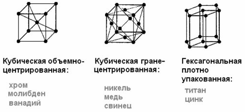
These collisions generate heat. This can be imagined as if you were walking through a crowd (great resistance), where they were pushing you, or if you were walking along an empty corridor, where you sweat harder?
The same thing happens with metal. Power is released as heat. In some cases, this is bad, because the efficiency of the device is reduced.In other situations, this is a useful property, for example in the work of heating elements. In incandescent lamps, due to its resistance, the spiral heats up to a bright glow.
But how does this relate to resistors?
The fact is that resistors are used to limit the current when feeding any devices or circuit elements, or to set the operating modes of semiconductor devices. We described it in an article on bipolar transistors. From the formula above, it will become clear that the current is reduced due to voltage reduction. Excessive voltage can be said to burn out in the form of heat on the resistor, while the power is considered by the same formula as the total power:
P = U * I
Here U is the number of volts "burned" on the resistor, and I is the current that flows through it.
The heat generation on the resistor is explained by the Joule-Lenz law, which relates the amount of heat released to the current and resistance. The larger the first or second, the more heat will be released.
To make it convenient from this formula, by substituting Ohm's law for a section of the chain, two more formulas are derived.
To determine the power through the applied voltage to the resistor:
P = (U ^ 2) / R
To determine the power through the current flowing through the resistor:
P = (I ^ 2) / R
A bit of practice
For example, let's determine how much power is allocated to a 1-ohm resistor connected to a 12V voltage source.
First, let's calculate the current in the circuit:
I = 12/1 = 12A
Now power according to the classical formula:
P = 12 * 12 = 144 watts.
One action in the calculations can be avoided if you use the above formulas, let's check this:
P = 12 ^ 2/1 = 144/1 = 144 W.
It all fits together. The resistor will generate heat with a capacity of 144W. These are conditional values taken as an example. In practice, you will not find such resistors in electronic equipment, with the exception of large resistances for regulating DC motors or starting powerful synchronous machines in asynchronous mode.
What are the resistors and how are they indicated on the diagram
A number of resistor capacities is standard: 0.05 (0.62) - 0.125 - 0.25 - 0.5 - 1 - 2 - 5
These are typical values of common resistors, there are also large values, or other values. But this series is the most common. When assembling electronics, an electrical circuit is used, with the serial number of the elements. Nominal resistance is indicated less frequently, and nominal resistance and power are indicated even less often.
To quickly determine the power of the resistor in the circuit, the corresponding UGOs (graphical conventions) were introduced according to GOST. The appearance of such designations and their interpretation are presented in the table below.
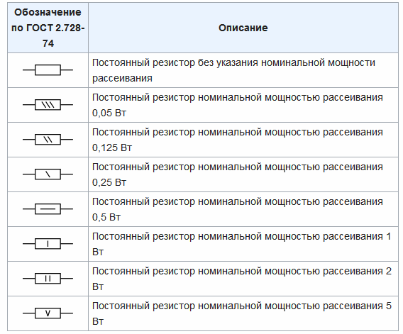
In general, these data, as well as the name of a specific type of resistor, are indicated in the list of elements, the allowed tolerance in% is also indicated there.
Outwardly, they differ in size, the more powerful the element, the larger its size. A larger size increases the heat exchange area of the resistor with the environment. Therefore, the heat that is released when the current passes through the resistance is quickly given to air (if the environment is air).
This means that the resistor can heat up with more power (to release a certain amount of heat per unit time). When the resistance temperature reaches a certain level, the outer layer with the marking begins to burn out, then the resistive layer (film, wire or something else) burns out.
To evaluate how much a resistor can heat up, take a look at the heating coil of a disassembled powerful resistor (more than 5 W) in a ceramic case.
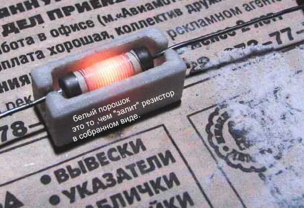
In the characteristics there was such a parameter as the permissible ambient temperature. It is indicated for the correct selection of the element. The fact is that since the power of the resistor is limited by the ability to transfer heat and, at the same time, not to overheat, but to transfer heat, i.e.cooling the element by convection or forced air flow should be as large as possible the difference in temperature of the element and the environment.
Therefore, if the element is too hot around the element, it will quickly heat up and burn out, even if the electric power on it is below the maximum dissipated. The normal temperature is 20-25 degrees Celsius.
Continuing this topic:
How to lower the voltage with a resistor
Calculation and selection of a resistor for the LED
Calculation of the voltage divider on the resistors
The use of additional resistors
What if there is no resistor of the required power?
A common problem with hams is the lack of a resistor of the required power. If you have more powerful resistors than you need - there is nothing wrong with that, you can set it without hesitation. If only he fit in size. If all the available resistors in power are less than necessary, this is already a problem.
In fact, solving this issue is quite simple. Remember the laws of series and parallel connection of resistors.
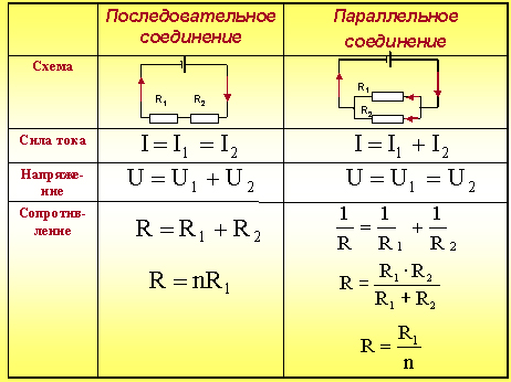
1. With a series connection of resistors, the sum of the voltage drops across the entire circuit is equal to the sum of the drops in each of them. And the current flowing through each resistor is equal to the total current, i.e. ONE current flows in the circuit from series-connected elements, but the DIFFERENT voltages applied to each of them are determined according to Ohm's law for the circuit section (see above) Utotal = U1 + U2 + U3
2. With a parallel connection of resistors, the drop across all voltages is equal, and the current flowing in each of the branches is inversely proportional to the resistance of the branch. The total current of the chain of parallel-connected resistors is equal to the sum of the currents of each of the branches.
This picture shows all of the above, in a convenient form for remembering.
So, as with a series connection of resistors, the voltage on each of them decreases, and with a parallel connection, the current, then if P = U * I
The power allocated to each of them will decrease accordingly.
Therefore, if you do not have a 100 Ohm to 1 W resistor, you can almost always replace it with 2 50 Ohm and 0.5 W resistors connected in series, or 2 200 Ohm and 0.5 W resistors connected in parallel.
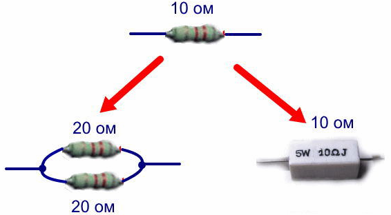
I just wrote “ALMOST ALWAYS”. The fact is that not all resistors carry shock currents equally well, in some circuits, for example, connected with the charge of large capacitors, at the initial moment of time they transfer a large shock load, which can damage its resistive layer. Such bundles must be checked in practice or by long calculations and reading technical documentation and specifications for resistors, which almost never and no one does.
Conclusion
The power of a resistor is no less important than its nominal resistance. If you do not pay attention to the selection of resistances you need power, then they will burn out and get very hot, which is bad in any circuit.
When repairing equipment, especially Chinese, in no case try to put resistors of lower power, it is better to put with a margin, if there is such an opportunity to put it in size on the board.
For stable and reliable operation of the electronic device, you need to select the power, at least with a margin of half the expected, or better, 2 times more. This means that if, according to calculations, 0.9-1 W is allocated on the resistor, then the power of the resistor or their assembly should be no less than 1.5-2 W.
See also at bgv.electricianexp.com
:
