Categories: Practical Electronics, Novice electricians
Number of views: 48979
Comments on the article: 2
Fundamentals of Electrical Engineering for Computer Modding Lovers
This article is for guidance only. The author is not responsible for any damage caused to the reader after reading it.
To begin with, everything in our computer works only because voltage, current is supplied to it :). Because of this, a number of processes and mechanisms are occurring, but we will not go deep. Where does this tension come from? Of course, from the Power Supply Unit (PSU). Its power is expressed in watts (watts).
Typically, power supplies go at least 250W, now they are increasingly installing a 300-350W power supply. Depends on its power, how many devices can be connected to your PC. In addition, there is such an indicator as the current strength in the circuit. But, as a rule, even in low-power PSUs there is a rather large current strength and this issue should not bother you. Also, power supplies can be of 2 types: AT or ATX. AT was used on older systems; ATX now dominates.
Well, let's proceed directly to the electrical work :).
Attention! Before you begin, you need to turn off the computer and preferably from the outlet, otherwise it will be a light electroshock :). If you try yourself in this business for the first time, then it would not hurt to test your crafts on a separate power supply, which is not connected to the motherboard and other devices.
Before connecting a new-made chip for testing to the power supply, it is necessary to insulate all open sections of wires and soldered parts. To do this, usually use either an insulating tape (electrical tape) ...
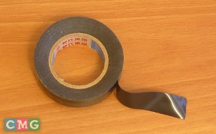
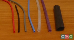
... either shrink tube (cambric), it comes in different diameters and contracts when heated. Otherwise, it doesn’t go out of the blue, it came to ignition.
Computer devices are connected through a special connector - molex.
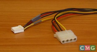
MOLEX (Molex) - a standard four-pin connector from the PSU, and also (much less often) - a three-pin connector for connecting a cooler. Probably both connectors were invented by Molex, hence the name ...
Similarly, all other devices we will be powered from molecules. Here is his visual photo:
And here is a schematic illustration:

As you can see, there are 4 contacts on it: 5V, "-", "-" and 12V. To connect our modding chips, you can use both 5V and 12V, depending on the desired voltage. In order to lower the voltage, for example to connect an LED, resistors are used.
RESISTOR (born resistor, from lat. resisto - I resist), a radio or electrical product whose main purpose is to provide a known active resistance to electric current. The resistor is characterized by a nominal resistance value (from several ohms to 1000 GΩ) and a maximum dissipation power (from hundredths of a W to several hundred W). The resistor is constant (its resistance is constant) and variable (the resistance can be changed within certain limits).
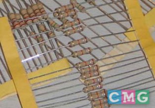
Later, on the example of connecting the LED, we will consider the use of resistors in modding, but for now we will consider the principles of connecting resistors:
1. Serial (useful if you do not find the necessary resistors, but there will be others with a lower rating).

When connected in series, the resistors simply add up: 150 + 150 + 250 = 550 Ohms.
2. Parallel (useful if you do not find the necessary resistors, but in the presence there will be others with a larger rating than necessary).
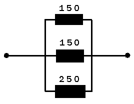
Here it is more difficult to consider:
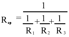
R (average) = 1 / (1/150 + 1/150 + 1/250) = ~ 57.69 = ~ 58 Ohms
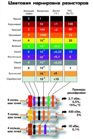
The program that determines the denomination by color marks is Rezistor.
For those who did not understand this program, there is such a table:
Light emitting diode (LED, electroluminescent diode), a semiconductor device with an electron-hole transition or a metal-semiconductor contact that generates (when an electric current passes through it) optical radiation, which in the visible region is perceived as monochromatic. It is used in indicator devices, information display systems, etc .; promising in optical communication, etc.

LED Power:
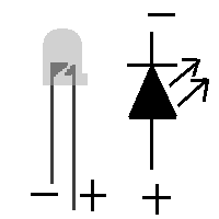
Typically, this scheme works: a long leg - anode (plus), short - cathode (minus). But it happens that the LED was removed from the case or from another device and there the legs are most likely already shortened. To do this, I would advise checking the diodes before soldering with a 3V battery the size of a tablet in a diameter of 2 cm:
It is almost impossible to burn a single diode, which is sold in our radio parts stores, and its size is the most convenient option from all that I have been offered before.
Typical LED Supply Voltage:
Red: 1.6V
Green: 2.1V
Yellow: 2.1V
Orange: 2.5V
Blue: 3.5-5V
Let's repeat the physics course for grade 8 and remember how to connect LEDs and resistors:
1. The resistor is connected in series with the LED:
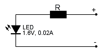
The current of a conventional LED is ~ 20 milliamps = 0.02 amperes. Suppose the voltage of the diode is 3 volts, and the total voltage is 5 volts. Then we first calculate what voltage drop the 5V-1.6V = 3.4V resistor should provide. And then, according to Ohm's law, we calculate the value of the resistor: R = U / I = 3.4V / 0.02A = 170Ohm. Now we are looking for the nearest factory value, and boldly buy it. In principle, there is always a face value that differs from a given value by no more than 5%, you just need to look well. For example, the nearest one is 180 Ohms.
2. Serial connection of 2 LEDs and a resistor.
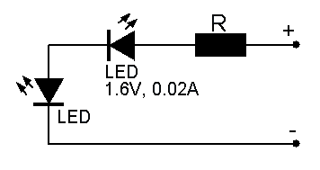
Here the principles are all the same, but just keep in mind that now the resistor should provide a smaller voltage drop (namely, 5V-1.6V-1.6V = 1.8V). According to Ohm's law: R = U / I = 1.8V / 0.02A = 90Ohm. Nearest factory rating: 82 Ohm.
From these two straightforward examples, we see that everywhere we used the same formula to find the value of the resistor - R = U / I.

With a parallel connection, unlike the serial, the voltage will be the same for all diodes, regardless of how many they are connected and equal to our 1.6V, but the current strength will increase in direct proportion to the number of our LEDs, and we have two of them (that is, like this: 0 , 02A + 0.02A = 0.06A) So, the voltage drop: 5V – 1.6V = 3.4V. According to Ohm's law: R = U / I = 3.4V / 0.06A = 56Ohm.
To consolidate the studied material :) consider how to reduce the noise emitted from a standard computer fan.
This is done in 2 ways:
1. Lubricate it.
2. It is necessary to lower the voltage on it.
Attention: With a decrease in voltage, the fan rotation speed decreases, which, of course, reduces the noise emitted, but, most importantly, reduces the air flow. What can adversely affect the temperature inside the system unit.
We will not dwell on the first method in detail, since it does not apply to this article. And let's talk about the second method a little more. There are two ways to lower the voltage:
Firstly, you can solder a resistor into the power circuit (the calculation formulas are the same as for connecting the LEDs), or you can get 7 volts directly from the power supply.
A conventional fan runs on 12 volts. So initially it was connected:
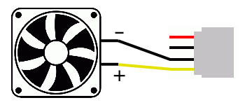
It is still possible to connect via a 3-pin connector, but the principle is the same - 12V and "-". Usually on fans “+” is a red (!) Wire, and “-” is black.
If we solder the resistor into the circuit, then we need to do this from "+" to "-" (the resistor is indicated in blue):
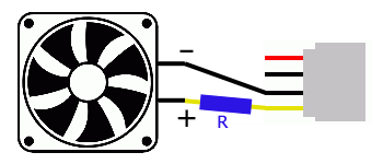
Conventional 80 mm fans have these characteristics: a voltage of 12V and a current of 0.11A. Therefore, we calculate according to the formula of what nominal value we need a resistor to lower the voltage to 7V: R = U / I = (12V-7V) /0.11A=45ohm. You can also lower the voltage to 10V, 8V, 5V, etc.
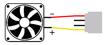
But there is another way to lower the voltage without resorting to resistors. As mentioned earlier - get 7V from the PSU.To do this, we need to re-solder one power wire, or rather black (ie “-”) from the fan to the red one on the molex connector:
Summarize. After reading the article you should know electrical engineering guidelines, which you can’t do without modding, and you can safely try soldering the LEDs on the front panel of the case and assemble a variety of devices such as fen, bay, reo-bass, etc. (articles about their assembly you can find on sites dedicated to modding).
See also at bgv.electricianexp.com
:
