Categories: Interesting electrical news, Electrician at home
Number of views: 105692
Comments on the article: 10
Pulse relays for lighting control and their use
Often, one switch is not enough to control the lighting, for example, when you need to turn on the light at the beginning of a long corridor and turn it off when you reach the end. This is realized by installing pass-through switches, quite simply, you just need to lay a three-core cable between them. But if you need to implement lighting control from more places, there are difficulties with laying wires to the cross switches, their connection ... It is much easier to use a special relay in such schemes. In this article we will consider what a pulse relay is and how to work with it.
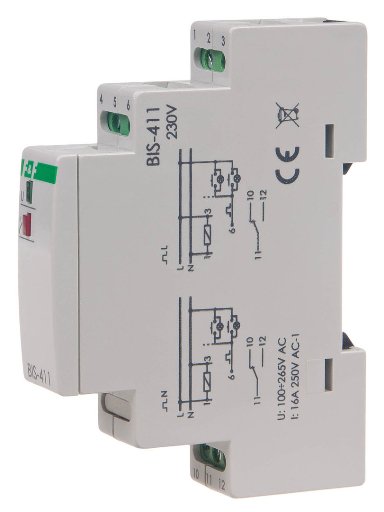
What is it?
Conventional relays work simply when voltage is applied to the coil - the contacts close (or open), when not, they return to their original position. In pulse relays, or as they are also called - bistable - this is not the case. When a voltage pulse is applied to the relay, it turns on; when the next pulse is applied, it turns off.
Conventional bistable relays are used in automation and security systems, when a pulse of one polarity is applied - the relay arm moves to one position, closing a pair of contacts, and when a pulse of reverse polarity is applied, the reverse process occurs - the armature goes in the opposite direction, switching contacts.
Impulse relays are:
-
electronic, they have a board with a microcontroller and a power semiconductor key - a triac.
-
Electromagnetic - they have an electromagnetic coil and a switching relay mechanism.
Principle of operation
Pulse relays for lighting control operate in 220V AC circuits. First of all, it is used to implement lighting control circuits from different places. To begin, consider how to do this without a relay - using walk-through and cross switches.
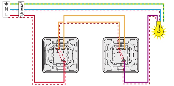
Light control scheme from 2 places:
Light control scheme from 4 places:
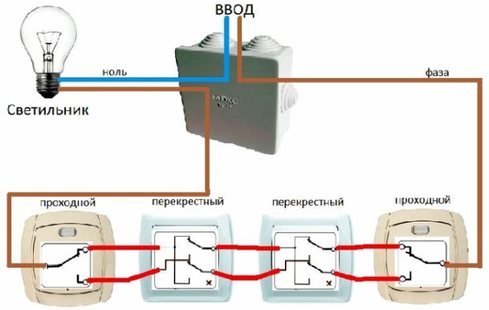
The main disadvantage of such schemes is the large number of cables that are necessary for its implementation, as well as the difficult installation.
To solve this problem, you can use a pulse relay. A conventional relay of any type is turned on when voltage is applied to its coil, and a short-time voltage supply is sufficient for a pulse, i.e. pulse.
This introduces the first requirement - to control a pulse relay, circuit breakers without fixing are needed, in other words, circuit breakers with a return spring. Buttons that are used for doorbells can also be used (they are also buttons without fixing).
Pulse relays are available in several varieties: for DIN rail mounting, in a dose (soldering) box, for mounting directly into the lamp itself. Some manufacturers of lighting equipment complete their luminaires with pulse relays, as a result of which it is possible to control several groups of lamps with one switch on a two-wire line.
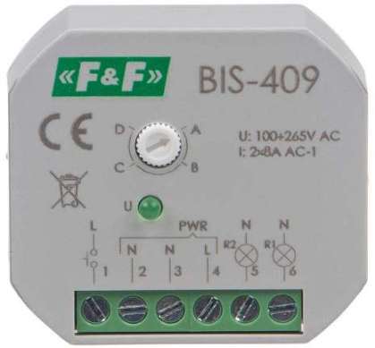
In addition to simple pulse relays designed for simple switching on and off, there are pulse relays with a built-in timer. Use such devices optimally on flights of stairs, walkways, in rooms with many doors.
For an example, we will consider one of the popular models of such a relay - Meander RIO-1.
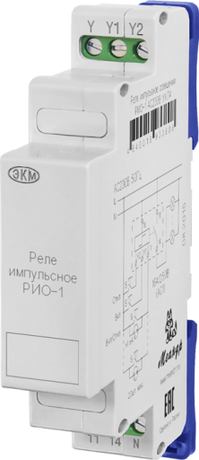
It has three control inputs, they are indicated by the letters "Y", "Y1", "Y2" located in the upper part of the case, and three terminals for power supply and load connection "11", "14" and "N".
Terminal assignment:
-
11, 14 - contact group, a phase is supplied to one of them, and a load is connected to the other.
-
Y - “Enable / Disable”.When voltage (phase) is applied to this input, the relay switches from on to off and vice versa, depending on the current state. It has no priority over the rest.
-
Y1 - “Enable”. When voltage is applied to this terminal, the relay contacts close, if they are already closed, nothing happens. It takes precedence over input Y, that is, if there is a signal on it and you apply a pulse to this input, then the relay contacts will close if they are open.
-
Y2 - “Turn Off”. It takes precedence over other inputs, when a signal is applied to it, the circuit is forced to open.
-
N - Neutral (zero) wire.
Contacts 11 and 14 are closed at the moment the phase passes through zero, this extends the service life of the contacts and lamps connected to them, due to the fact that during such a switch the inrush current is limited. The technical characteristics of the pulse relay are shown in the table below.
The first thing you should pay attention to is that the minimum holding time of the control signal is 0.3 s. This is important if you are designing a microcontroller circuit to control this relay. In the case of use in the classic version with switches, this does not matter much.
The next interesting point is “the number of push-button switches with a glow discharge indicator,” as you know, in order for the backlight to work on the switches, current must flow through them. If you use incandescent lamps - this does not really matter, because the current will go through the circuit - phase, indicator, lamp, zero. But if you use LED or compact fluorescent tubes, then they begin to flash off or even glow.
In the case of the internal device of the relay, its sensitivity to the input current allows you to connect from 5 to 20 such switches, depending on the input. Refer to the table above for specific values.
RIO-1 is capable of switching currents up to 16A or incandescent lamps with a capacity of up to 2000W.
Consider the timing diagram of RIO-1.
A time chart is a chart that displays the dependence of the state of the outputs on the input signals.
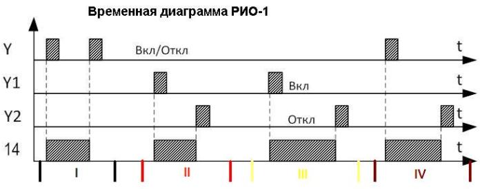
What is depicted on it? Assume that the relay is used as intended and turns on the light bulb.
For a plot designated as "I":
1. We give a pulse to Y - at output 14 (the contact to which the load is connected), the voltage appears; the lamp turns on.
2. Once again we give a pulse to Y - at the output 14 the voltage disappears, the lamp goes out.
For plot "II" and "III":
1. We give a pulse to input Y1 - voltage at terminal 14 appears, the lamp turns on.
2. We give a pulse to input Y2 - the voltage at terminal 14 disappears, and the lamp turns off.
For site "IV":
1. We give a pulse to input Y - the voltage at terminal 14 appears, the lamp turns on, if you now apply a second pulse to the same terminal, it will turn off.
2. We give a pulse to input Y2 - the lamp turns off.
Why is this needed? Firstly, it is convenient if you have several such relays installed, by connecting one shutdown button for all the lamps to the Y2 contacts of each relay, you can turn them off all together regardless of the state (on or off) of each of them. In the same way, it is possible to realize the inclusion of groups or all lamps in the room from one button and the turn-off and so on.
If for controlling, for example, a luminaire using passage switches from two or more places, it is necessary to lay three or more wires to the switches with a cross section corresponding to the power of the luminaire but not less than 1.5 mm square, then to control the same luminaire using a pulse relay, it is necessary to lay one two-core cable with a cross-section of 0.5 mm square, buttons like bell-type ones with normally open contacts are suitable as control mechanisms (switches).
As a result, during the installation process, considerable savings are obtained on materials, especially when you consider that the prices for cable products are increasing daily, plus the cost of the passage switches themselves must be added to the cost of cables.
An example is shown in the video:
To save your time, you can immediately rewind the video for 5 minutes, where the demonstration of the chain starts.
Wiring diagram
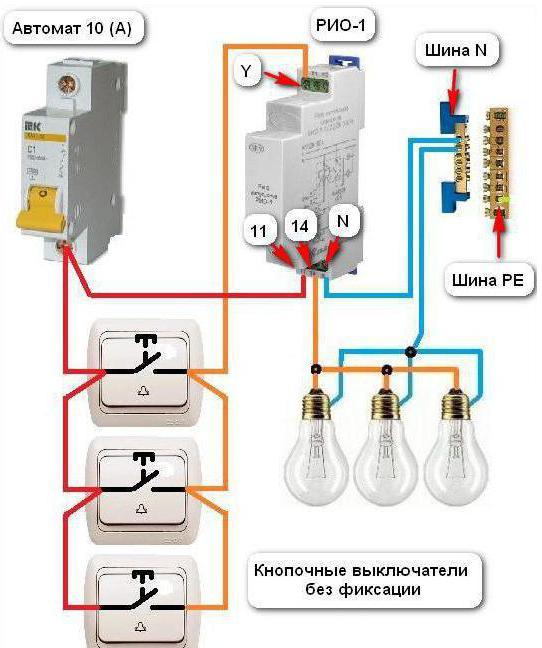
The relay is supposed to be used in schemes for turning off the light from several places, for its implementation it is enough to conduct a two-wire thin wire to each of the switches without fixing, up to 2x0.5, because this is a control signal, not a power circuit.
Power supply wires are connected to the switching contacts of the relay. It does not matter how many and how many places the circuit breakers can be connected. Below is a simple circuit with three switches.
Another scheme differs from the previous one in that in the first group each group of lamps can be controlled from three places. In addition, all lamps of both groups can be turned on or off from a pair of additional switches with one click, they are signed on the diagram as “ON.” and “OFF.”
This is convenient if you place these switches near the front door and when you get home, you can immediately turn on the lights in the entire apartment, or click on “OFF.” so that all probably put out all the lights in the house.
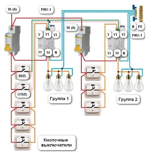
If you intend to use this relay in pair with motion sensor, then you need to provide that when the sensor trips, the relay turns on and the light comes on, when you leave the field of view of the sensor, after some time it will remove the control signal, and the light will continue to light. Therefore, it is necessary to provide a button for turning off the light and forcing the light on. They are connected to the contacts Y1 - on and Y2 - off, respectively.
Pulse sectional relay
A separate word needs to be said about sectional relays, they are designed to turn on different groups of lamps or all groups at the same time with one button. So you can control a multi-track chandelier in two wires, and you do not have to lay additional wiring to it from the switch.
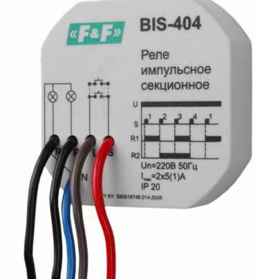
The connection diagram is indicated on the case of this relay (in a particular case, two buttons are drawn, that is, control from two places is assumed) and a time diagram, it is designed for two groups of lamps:
-
First press - turns on 1 group of lamps;
-
The second press - turns on 2 groups of lamps, and 1 group turns off;
-
Third press - the second group of lamps remains on, but 1 group is added to it (all lamps are on);
-
A fourth press turns off all the lamps.
Conclusion
We examined pulse relays for lighting control. These devices will greatly simplify the installation of electrical wiring and ensure the normal functioning of the fixtures. Sectional relays eliminate the need for wiring for a multi-track chandelier. They can also be used in smart home circuits and other automation control lighting.
See also at bgv.electricianexp.com
:

