Categories: Sharing experience, Practical Electronics, Electrician at home
Number of views: 35619
Comments on the article: 1
How to make a simple status indicator of a remote lamp
 At one time, I was faced with the need to control the burning and integrity of the light bulb when the switch is in another room (for example, a basement, cellar or chicken coop). More than once it happened, the switch is turned on, and the light does not light up: it either burned out, or the contact in the cartridge or switch disappeared. In this case, the switch is located in the corridor, and to the basement, where hens live, you need to go around the house.
It is especially bad when, because of this, the bird does not enter the basement in the evening, and then it must be entered manually. The problem was solved by installing a simple and trouble-free device that indicates the flow of current in the circuit of the lighting lamp and is located near the switch.
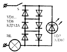
The indicator diagram is shown in the figure, where S - light switch; HL - a lighting lamp with a power of 60-100 W; VD1 ... VD6 - ballast diodes; VD7 - LED indicator. When current flows through ballast diodes, a voltage sufficient for the LED to glow is incident on them.
You can connect the device at any convenient point in the electrical circuit (before or after the switch) or to break the second wire leading to the lamp.
The indicator is not critical to details. As ballast diodes, you can use any small-sized diodes with a permissible direct current not lower than the illuminator current consumption and any operating voltage (for lamps with a power of 60-150 W, you can use KD208, KD209, KD212, KD215, KD217, etc., and for lamps power up to 60 W - KD105, KD106, D226, D237, etc.).
A more powerful load will require more powerful diodes, with two diodes in each branch. The LED must have a constant forward voltage of 1.7 ... 2.2 V at a current of at least 10 mA. Of domestic LEDs, AL307A, B satisfy these requirements, of imported almost any with a red, orange or yellow color.

Remote status indicator circuit
The design of the indicator leaves room for creativity. With a great desire and some sophistication, it can be placed even in the case of the switch itself. The author has installed the device separately from the switch (but next to it) so that it can be seen from afar. The board with the clamps for connecting the wires is mounted in a plastic case (a children's cube), the LED lens through the hole in the wall is brought out. The indicator has been working smoothly for six months.
See also at bgv.electricianexp.com
:
