Categories: Sharing experience, Practical Electronics
Number of views: 40261
Comments on the article: 0
Home-made device for protecting the motor from under-phase conditions and overload
 As typical elements of motor protection, electrothermal relays are most often used. Designers are forced to overestimate the rated current of these relays, so that there are no trips at startup. The reliability of such protection is low, and a large percentage of engines fail during operation.
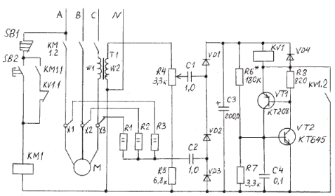
The circuit of the motor protection device (see the figure) from out-of-phase modes and overload is characterized by increased reliability. Transistors VT1, VT2 together with the elements connected to them form an analog of a dynistor, the switching voltage of which (Uin) depends on the ratio R6 / R7. With the ratings indicated on the diagram 30 V < Uon <36 V in the temperature range -15 Resistors R1 ... R3 form a vector adder, at the output of which the voltage is 0, if the motor is full-phase. The transformer T1 is a current sensor of one phase of the electric motor. The outputs of the current sensor and vector adder are connected to a rectifier made on diodes VD1 ... VD3. In normal mode, the voltage at the rectifier output is determined by the current in the primary winding T1 and the ratio of turns wl / w2. Using a resistor R4, this voltage is set below U on VT1 and VT2.
If phase failure or motor overload occurs, then voltage at the rectifier output it will exceed Uon, transistors VT1, VT2 will open, and relay KV1 will be energized. KV1.1 contacts will break magnetic starter lockout circuitand the engine will turn off. KV1.2 contacts block transistors VT1 and VT2, preparing the circuit for the next cycle of work. The response speed of the protection depends on the capacitance of the SZ capacitor. The duration of the switching pulse of the relay KV1 depends on the resistance of the winding KV1 and the capacitance of the capacitor SZ. Within certain limits, the speed of protection can be changed by selecting the values C1, C2, R1 - R3.

All parts except R1 ... R3 and T1 are mounted on a printed circuit board. After assembling the board, you need to connect a voltmeter to the SZ and, applying an alternating voltage of 20-24 V to one of the inputs of the rectifier (C1 or C2), check the switching voltage VT1 and VT2. If necessary, select the resistance of the resistor R6. Relay KV1 will periodically turn on. Finalize the scheme on the current engine. First, you need to select the number of turns w1 within 1-10 turns (depending on engine power), so that in normal mode 22-24 V are supplied to the R4, R5 chain. Resistor R4 sets the overload protection threshold. If triggering occurs at start-up, then it is necessary to increase the capacitance of the SZ capacitor without changing the position of the R4 engine. After that, check the operation of the circuit, simulating an in-phase mode.
As rectifier diodes VD1 ... VD4, any rectifier diodes with Ure> 100 V and a current of more than 30 mA can be used. Transistors VT1, VT2 can be replaced by KT361 or KT315. KV1 relay for 24 V with contacts suitable for switching in 220 V AC circuits.
In the T1 transformer, it is best to use a collapsible tape core core with a section of 2-4 cm2. The secondary winding can be wound with a wire of 0.15-0.2 mm 1000-1500 turns, and the primary one with a mounting wire of a suitable section. Resistors R1 ... R3 must be installed directly on the engine, filling them with bitumen to protect against moisture.
See also at bgv.electricianexp.com
:
