Categories: Sharing experience, All about LEDs
Number of views: 168995
Comments on the article: 24
Homemade LED Strip Light
 The topic of LED lighting is, recently, one of the most popular. In most cases, on the Internet, among home-made light sources, I had to meet lamps made of separate LEDs and installed in a defective housing energy saving lamp together with the power supply.
This arrangement allows the use of an LED lamp instead of a conventional incandescent lamp without any alteration of the lamp. Relative complexity must be recognized as some drawback of this design. pcb manufacturingwhich usually has the shape of a circle. An example of the implementation of a home-made LED lamp made of individual LEDs is shown in Fig. 1.
At the same time, nowadays they have gained very wide popularity. led strip. But, as a rule, they are used mainly for decorative lighting and very rarely - as lighting. However, if not for main lighting, then for local illumination of certain areas, the use of LED strips can be quite effective. Therefore, today we will talk about creating a simple homemade lamp based on LED strip.
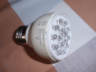
Fig. 1.Homemade LED lamp made of individual LEDs
LED Strip Light - This is a flexible "printed circuit board" on which the frameless LEDs and current limiting resistors. The design of the tape allows you to cut the necessary pieces from it, depending on the specific requirements. Near the cut line there are contact pads to which the power wires are soldered. On the reverse side, a self-adhesive film is applied to the LED strip. The most popular are 12V-powered tapes.
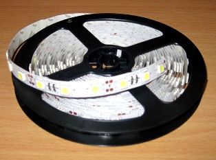
At one time, I ordered on ebay.com a waterproof LED strip 5050 SMD LED Strip (Fig. 2).
Fig. 2LED Strip Waterproof 5050 SMD LED Strip
This LED strip has the following characteristics: light emission angle - 120 degrees; supply voltage - 12V; current consumption - 1.2A per 1 meter; luminous flux - 780-900 Lm / m protection class - IP65
For almost a year the tape lay idle, but when the electronic ballast (electronic ballast) for the second time "flew out" in the fluorescent lamp used to illuminate the workplace near the computer, I realized that I needed to switch to more modern ways of organizing lighting.
The same failed lamp for 8 W fluorescent lamps with a length of 30 cm was used as a housing. Its conversion to the “LED version” is very simple.
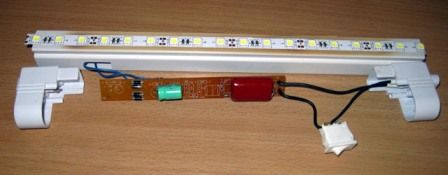
We disassemble the lamp, remove the electronic ballast board and stick an LED strip on the inner surface of the lamp. A total of six segments with three LEDs in each segment, or a total of 18 LEDs, installed with an interval of 15 mm between them (Fig. 3).
Fig. 3 General view of a homemade LED lamp
It is not necessary to throw out the faulty electronic ballasts; its printed circuit board can be used for the power supply unit of our lamp. And not only the board, but also some of its components (of course, provided that they remain intact), for example, a diode bridge. Let us dwell on the power supply unit in more detail.
To power the LEDs, it is necessary to use power supplies with current stabilization. Otherwise, the LEDs will gradually warm up to a critical temperature, which will inevitably lead to their failure.
The most simple and optimal solution in our case would be to use a transformerless power supply with a ballast capacitor (Fig. 4).
Fig. 4 Schemetransformerless power supply with ballast capacitor
The mains voltage is suppressed by a ballast capacitor C1 and fed to the rectifier, assembled on diodes VD1-VD4.From the rectifier, a constant voltage is supplied to the smoothing filter C2.
Resistors R2 and R3 are used to quickly discharge capacitors C1 and C2, respectively. Resistor R1 limits the current at the time of switching on, and the zener diode VD5 limits the output voltage of the power supply to no more than 12V in the event of an open LED strip.
The main element of this circuit, which requires calculation, is the capacitor C1. It is on its rating that the current that the power supply can provide is determined. The easiest way to calculate is to use a special calculator.
The maximum current, according to the passport data, for a length of a segment of an LED strip of 30 cm should be 1.2 A / 0.3 = 400 mA. Of course, you should not power the LEDs with maximum current.
I decided to limit it to approximately 150 mA. With this current, the LEDs provide the optimal (for subjective perception) glow with little heating. Entering the initial data into the calculator, we obtain the value of the capacitor C1 equal to 2.079 μF (Fig. 5).

Fig. 5 Calculation of the capacitor for the power supply circuit of a homemade LED lamp
We choose the closest standard capacitor rating relative to the one calculated. It will be a nominal 2.2 uF. The voltage for which the capacitor is designed must be at least 400V.
After calculating the ballast capacitor and selecting the elements of the power supply circuit, we place them on the board of the faulty electronic ballast. It is advisable to remove all unnecessary parts (except for the bridge of four diodes). The appearance of the power supply board is shown in Fig. 6.
Fig. 6The appearance of the power supply board
We connect the LED strip to the power supply, turn it on to the network, and check the homemade lamp in operation.
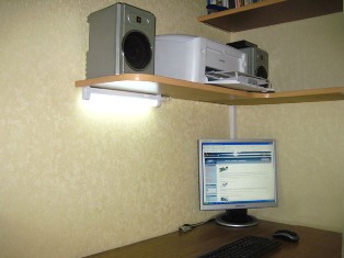
After mounting and checking the operation of the power supply, install it in the housing and place the upgraded lamp from the LED strip in place of continuous operation (Fig. 7).
Fig. 7 Homemade LED Strip Light
Attention! This power supply circuit is transformerless and has no galvanic isolation from the mains. During installation and commissioning it is necessary to strictly observe the safety regulations. The power supply must be installed in a casing made of insulating material, it is necessary to ensure the impossibility of touching its live parts during operation of the lamp.
Mikhail Tikhonchuk
See also at bgv.electricianexp.com
:

