Categories: Sharing experience, Novice electricians, Electrician Secrets
Number of views: 105588
Comments on the article: 6
Why do I need an oscilloscope?
 Sooner or later, any novice electronics engineer, if he does not give up his experiments, will grow to circuits where you need to monitor not just currents and voltages, but the operation of the circuit in dynamics. This is especially often needed in various generators and pulse devices. There is nothing to do without an oscilloscope!
Scary device, huh? A bunch of pens, some buttons, and even the screen and nifiga is not clear what is here and why. Nothing, we’ll fix it now. Now I’ll tell you how to use the oscilloscope.
In fact, everything is simple here - the oscilloscope, roughly speaking, is just ... voltmeter! Only cunning, able to show a change in the shape of the measured voltage.
As always, I will explain with an abstract example
Imagine that you are standing in front of a railway, and an endless train consisting of exactly the same cars is rushing past you at a frantic speed. If you just stand and look at them, then you will not see anything other than blurry garbage.
And now we put in front of you a wall with a window. And we begin to open the window only when the next car is in the same position as the previous one. Since we have the same wagons, it’s completely optional for you to see the same wagon. As a result, pictures of different but identical cars will pop up in front of your eyes in the same position, which means the picture will stop as it were. The main thing is to synchronize the opening of the window with the speed of the train, so that when you open the position of the car does not change. If the speed does not match, then the cars will “move” either forward or backward with a speed depending on the degree of desynchronization.
Based on the same principle strobe light - a device that allows you to examine fast moving or rotating horseradish. There, too, the curtain quickly and quickly opens and closes.
So, the oscilloscope is the same strobe, only electronic. And he does not show cars, but periodic changes in voltage. For the same sinusoid, for example, each subsequent period is similar to the previous one, so why not “stop” it, showing one period at a time.
Oscilloscope Design
This is done through ray tubedeflecting system and sweep generator.
In a beam tube, an electron beam entering the screen makes the phosphor glow, and the plates of the deflecting system make it possible to drive this beam over the entire surface of the screen. The stronger the voltage applied to the electrodes, the more the beam deflects. Feeding on a plate X sawtooth voltage we create a scan. That is, the beam moves from left to right, and then abruptly returns and continues again. And on the plate Y we apply the studied voltage.
The principle of operation of the oscilloscope
Then everything is simple, if the beginning of the appearance of the saw period (the beam is in the extreme left position) and the beginning of the signal period coincide, then in one pass of the sweep one or several periods of the measured signal are drawn and the picture seems to stop. By changing the sweep speed it is possible to achieve that only one period will remain on the screen - that is, one period of the measured signal will pass in one saw period.
Synchronization
You can synchronize the saw with the signal either manually, adjusting the speed knob so that the sine wave stops, and possible by level. That is, we indicate at what level of voltage at the input you want to run the sweep generator. As soon as the input voltage exceeds the level, the sweep generator will immediately start and give us an impulse.
As a result, the sweep generator issues the saw only when necessary. In this case, the synchronization is completely automatic. When choosing a level, a factor such as interference should be considered.So if you take a level too low, then small needles of interference can start the generator when you do not need it, and if you take a level too high, the signal can pass under it and nothing will happen. But here it’s easier to turn the knob yourself and immediately everything will become clear.
Also, the synchronization signal can be supplied from an external source.
For details on how the oscilloscopes are arranged and work, see here: Electronic oscilloscope
So, into the furnace theory, we turn to practice
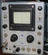 I will show by the example of my oscilloscope, stolen once upon a time from the defense enterprise of the Rotor Design Bureau :). The usual oscillation, not very sophisticated, but reliable and simple as a sledgehammer.
So:
The brightness, focus and lighting of the scale, I think, do not require explanation. These are the interface settings.
Amplifier U and up and down arrows. This knob allows you to drive the signal image up or down. Adding him an extra offset. What for? Yes, sometimes there is not enough screen size to accommodate the entire signal. We have to drive it down, taking for zero not the middle, but the lower border.
Below is a toggle switch switching input from direct to capacitive. This toggle switch in one form or another is on all without exception oscilloscopes. Important thing! Allows you to connect the signal to the amplifier either directly or through a capacitor. If connected directly, then the constant component and the variable will pass. And only the variable passes through the conder.
For example, we need to look at the noise level of the computer’s power supply. The voltage there is 12 volts, and the amount of interference can be no more than 0.3 volts. Against the background of 12 volts, these miserable 0.3 volts will be completely invisible. You can, of course, increase the gain along Y, but then the graph will come out of the screen, and there will not be enough displacement along Y to see the top. Then we only need to cut the capacitor and then those 12 volts of constant current will settle on it, and only an alternating signal will pass into the oscilloscope, the same 0.3 volt of interference. Which can be strengthened and seen in full growth.
Next is the coaxial connector for connecting the probe. Each probe contains a signal and ground. The earth is usually planted on minus or on the common wire of the circuit, and the signal is poked along the circuit. The oscilloscope shows the voltage on the probe relative to the common wire. To understand where the signal, and where the earth is enough to take their hand in turn. If you take up the general, then the screen will still be the pulse of the corpse. And if you take up the signal, you will see a bunch of srach on the screen - aiming at your body, which is currently serving as an antenna. On some probes, especially on modern oscilloscopes, a voltage divider of 1:10 or 1: 100 is built inside, which allows you to plug the oscilloscope even into a socket, without risk of burning it. It turns on and off with the toggle switch on the probe.
Almost every oscilloscope has a calibration output. On which you can always find a rectangular signal with a frequency of 1KHz and a voltage of about half a volt. Depending on the model of the oscillation. It is used to check the operation of the oscilloscope itself, well, sometimes it is useful for testing purposes :)
Two Hefty Twisters Gain and Duration
The gain is used to scale the signal along the Y axis. It also shows how many volts per division will ultimately show.
Say, if you have 2 volts per division, and the signal on the screen reaches a height of two cells of the dimensional grid, then the signal amplitude is 4 volts.
Duration determines the sweep frequency. The shorter the interval, the higher the frequency, the more high-frequency signal you can see. Here the cells are graduated in milli and microseconds. So by the width of the signal you can calculate how many cells it is, and multiplying it by the scale along the X axis you will get the signal duration in seconds. You can also calculate the duration of one period, and knowing the duration it is easy to find the signal frequency f = 1 / t
The top pipette on the twists allows you to change the scale smoothly. Usually it’s on my click so that I always clearly know what my scale is.
Also there is an input X to which you can apply your signal, instead of a sweep saw. Thus, the oscilloscope can serve as a TV or monitor, if you collect a circuit that will form an image. A spinner with the words Sweep and left and right arrows allows you to drive the chart on the screen left and right. It is sometimes convenient to fit the desired area for the division of the grid.
Sync block
Level knob - sets the level from which the saw generator will start.
The switch from internal to external allows you to apply clock pulses to an input from an external source.
A switch labeled +/- toggles the polarity of the level. Not available on all oscilloscopes.
Handle stability - allows you to manually try to choose the speed of synchronization.
Fast start
So, you turned on the oscillation. The first thing to do is to close the signal probe to your own earthen crocodile. In this case, “Pulse of the corpse” should appear on the screen. If it doesn’t appear, then turn the stabilization knobs and offsets and level - maybe it just hid behind the screen or did not start due to insufficient level.
As soon as the strip appeared, then set the twist to shift it to zero. If you have analog oscilloscope, especially if ancient, then let it warm up. After turning on, mine floats for another fifteen minutes.
Next, set the voltage measurement limit. Take with a margin, if you reduce anything. Now, if you attach the ground wire of the oscilloscope to the minus of the battery, and the signal to the plus, you will see how the graph jumps by one and a half volts. By the way, old oscilloscopes often begin to falter, so it’s useful to see how accurately it displays the voltage using a reference voltage source.
Oscilloscope Selection
If you just started, then anyone will do. It is highly desirable if it is dual-channel. That is, he will have two probes and two Gain twists, for the first and second channel, which allows you to simultaneously get two graphs.
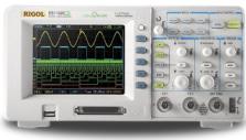
The second most important oscilloscope criterion is frequency. The maximum frequency of the signal that he can catch. So far, 1MHz was enough for me not to swing it. Those oscilloscopes that are sold in stores already have a frequency of 10 MHz or higher. The cheapest oscilloscope that I saw cost 5 thousand rubles - OSU-10. The two-channel one is already worth 10 thousand, but I aimed to take a digital RIGOL DS1042CD for kilobax. Different requests - different toys. But, I repeat, 1MHz is enough for a start, and enough for a long time. So find yourself at least some kind of oscilloscope. And there you will understand what you need.
See also on this topic: How to use the oscilloscope
See also at bgv.electricianexp.com
: