Categories: Featured Articles » Sharing experience
Number of views: 86188
Comments on the article: 22

How to make an LED from a compact fluorescent lamp
 

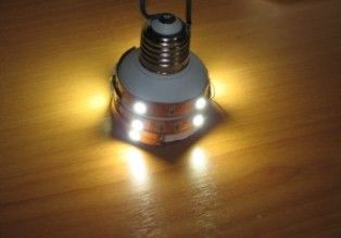
How to make an LED from a compact fluorescent lampFrom a burnt compact fluorescent lamp, you can make a replacement for it and at the same time it will be almost eternal. I will tell you how to do it.

Assembly: The burnt-out compact fluorescent lamp must be carefully disassembled and the new circuit soldered by hinged mounting directly inside the base. Leave the fuse that was in the lamp. Diodes 1N4007 are extracted from the board of the same lamp. To them we add a capacitor 1mkf 630 volt K73-17 and one electrolyte.

The electrolyte is suitable for almost any voltage of 50 volts or higher, well, and with a capacity of more than 100 microfarads. Still need 4 pieces led strip. As a rule, the tape is produced so that it can be divided into pieces of 12 volts.

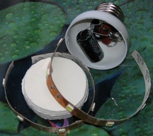
In this case, on one such piece 3 LEDs. Cut 4 pieces of 3 LEDs and turn them on sequentially. So that the parts do not hang out, inside the base they can be glued with any glue. Cut out a base extension from some material. I used foam board - it is easy to process.
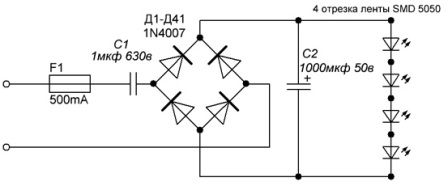
Homemade LED lamp power circuit
Homemade LED lamp power circuit

LED lamp assembly

LED lamp assembly

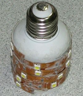
Below in the photo is an almost finished “eternal” LED lamp. It remains to smooth out the irregularities with liquid nails and then dry, after which the tape will hide under the white liquid nails and it turns out that only the LEDs will look out.

While the liquid nails have not yet hardened, their surface can be made very smooth with water and the lamp will have a good appearance (almost like a real one). I put the same in the common corridor with my neighbors almost a year ago and since then I forgot how to change the bulbs.

Homemade LED lamp

Such an LED bulb already starts to glow quite well at ~ 40 volts, at 220 volts on a 3-diode segment 11.5 volts, and at 250 volts 12 volts, i.e. she is not afraid of any voltage drops.

It does not shine weakly. If each 5050 SMD chip gives approximately 10-15 lumens of brightness (in each 3 crystals as in 3528), then 120 ... 180 lumens are obtained. Perhaps the only drawback is galvanic communication with the network in an open form, i.e. when handling it, it is necessary to take this into account and take appropriate precautions.


And this is another, but it shines twice as much.

Another homemade light bulb, but 2 times more powerful than the previous one. It added another capacitor of 1 microfarad 630 volts in parallel to C1 and another 4 segments of 3 LEDs, which resulted in 24 LEDs and a total luminous flux of about 360 lumens.

Power scheme of a homemade LED lamp:
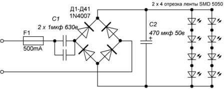
Homemade LED lamp power circuit

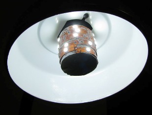
Ready-made LED lamp:

Ready LED Lamp

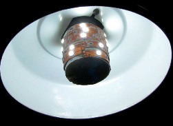
This bulb with Liquid Nails glue did not grease much. I inserted it into a table lamp. It shines so brightly that it overshadows daylight. (Photographed in a sunlit room)

How to make an LED from a compact fluorescent lamp

With a consumption of about 6 watts, this lamp shines much stronger than a 40 watt bulb, i.e. the lamp will not only last much longer energy saving lamps, but also consume several times less energy. I used cold white LEDs, but if you like warm ones, then such LED strips are also sold and you can apply them.

See also at bgv.electricianexp.com:

  • The ratio of the power of lamps of various types
  • How to make a backlit switch yourself
  • Homemade LED Strip Light
  • Illuminated magnifier: switch to LEDs
  • DIY LED spotlight

  •  
     
    Comments:

    # 1 wrote: Alex | [quote]


    It is dangerous to put such a light bulb in a common corridor with neighbors - it will be stolen. My usual incandescent bulbs go away once a week, and then kill the time, and then it’s not even a day's sag, as it’s almost exclusive.

     
    Comments:

    # 2 wrote: Shurochka | [quote]


    Yes. To modern neighbors it’s generally dangerous to put something)))
    The idea is interesting. But not everyone will sit, bathe with this light bulb. Glue, solder ... I went easier, bought it and that’s it!
    Although if you like to do something so man-made, it’s a very good idea!

     
    Comments:

    # 3 wrote: | [quote]


    4 segments of 3 LEDs, which resulted in 24 LEDs - how is it?

     
    Comments:

    # 4 wrote: andy78 | [quote]


    This one describes a modification of the lamp to increase its luminous flux (see the second diagram). That is, 4 segments of three LEDs connected in series in the first circuit + 4 segments of three LEDs additionally in the second circuit. (3 x 4) x 2 = 24 LEDs.

     
    Comments:

    # 5 wrote: | [quote]


    The scheme is too simple, but it works.

    Remarks:

    1. forgot to say about the insecurity of such devices.

    2. It is advisable to add a zener diode, which will protect the 50V capacitor if an LED circuit breaks.

    3. Instead of a fuse, just a 50-100ohm 1W resistor is installed. The resistor limits the starting current and at the same time serves as a fuse.

    4. The capacitance of capacitor C1 (1uF) is overstated. When using a diode bridge and several dozen series-connected diodes, its capacitance should be about 0.4 μF.

    ps look in the network for "circuits with a quenching capacitor" + "LED bulb".

     
    Comments:

    # 6 wrote: | [quote]


    Full crap, this is not for electricians, but for lovers to do something.

     
    Comments:

    # 7 wrote: Alexander 1 | [quote]


    Put an electrolytic capacitor of 50 volts in a circuit where, when the LED circuit breaks, a voltage of more than 300 volts appears (and the break will happen sooner or later) - this is to do a time bomb. Someday surely bum.

     
    Comments:

    # 8 wrote: Vasya | [quote]


    Alexander 1,
    What are 300 volts? Can you see the capacitor in front of the diode motor? A capacitor must be smaller capacity and put a resistor in front of it.

     
    Comments:

    # 9 wrote: Dmitriy | [quote]


    Power factor such lamps, especially in good numbers, will kill nafig on the network, the reactive power is expensive mom. The slogan is garne, tsil filth. Power supply must be done by a normal converter.

     
    Comments:

    # 10 wrote: | [quote]


    Dmitry is right!
    Shines for a couple of watts, consumes reactive power of 30 volt ampere reactive!
    Empty reactive power (from the capacitor to the substation and vice versa) is chased by wire!
    The normal circuit is a flyback converter with a combined power corrector (High PFC Flyback).
    People! DO NOT litter the power grid with simplest rectifiers and such housekeepers.

     
    Comments:

    # 11 wrote: | [quote]


    Andrew. And I spit on energy losses in the substation and on reactive power, too. Normal simple circuit. For the entrance just right. So as not to steal. And they’re stealing, though it’s not so pathetic as putting a factory lamp for 400 rubles.

     
    Comments:

    # 12 wrote: MaksimovM | [quote]


    Andrew,compensating devices are installed at substations for reactive power compensation. Well, if you judge, housekeepers and other household appliances consume a very small amount of reactive power, so this value is neglected. If there were large values ​​of reactive power, then the energy supply companies would be obliged to install metering not only active, but also reactive component.

    If we are talking about an industrial enterprise, then it is necessary to compensate for reactive power without fail, since the values ​​in this case are large.

    Although now at many substations compensating devices are disabled. If you look at the load of power lines, for example, 110kV transit lines, then some have an active load of 5MW and a reactive load of 3MVar! Energy supply companies do not take measures to compensate for the reactive load of 3 MVAr, and you worry about 30 VAr from the light bulb.

     
    Comments:

    # 13 wrote: | [quote]


    Thanks for the useful schemes, as soon as I repeat I will definitely write to you.

     
    Comments:

    # 14 wrote: Aryslan | [quote]


    Quote: Vasya
    A capacitor must be smaller capacity and put a resistor in front of it.

    Vasya, which is C1 or C2? What capacity is needed? How many ohms and how much power? Thanks!

     
    Comments:

    # 15 wrote: | [quote]


    Electricians ..... :) :) :)
    The network is dominated by negative (inductive) reactive energy.
    To compensate for it, they put capacitor blocks at the substation (but actually they are mostly turned off, because it happens, they swear, and who needs to bother with them, it’s dangerous - a conductor of 6 square meters or more with a capacity of microfarads is a terrible, deadly thing, like anti-personnel mine - whoever comes across knows. But the benefits are not visible ...).
    The power corrector circuit just contains a capacitor. Therefore, the inclusion of this light bulb in addition to the benefits to the network will not do any harm.
    Under the Soviet regime, large consumers (factories, factories, railways, etc.) demanded compensation for reactive power, and not because the losses were increasing - the wires were heating up, in fact, these losses did not wobble anyone. Just increased reactive power creates an alternating load on the generator shaft and increased vibration at the second harmonic, which leads to a decrease in the resource of the turbine and generator bearings. And most importantly, when several generators work in parallel and a high reactive power level, the generator can knock out of synchronism, which will lead to its shutdown and accident, and the "dispersal" of the energy system as a whole.
    But the energy system can’t be filled up with bulbs - we don’t have so many home-made hands. It's a pity :(

     
    Comments:

    # 16 wrote: gene | [quote]


    Hook the diode tape from the 12v atx computer and get down already.

     
    Comments:

    # 17 wrote: | [quote]


    At first glance, it’s the same housekeeper, it’s only shining))
    The capacitor does not consume reagent, but generates.

     
    Comments:

    # 18 wrote: Earring | [quote]


    The campaign gathered some defenders of state power networks. Despite the fact that a large half I am sure and have no idea where the reactive energy comes from and everything connected with it. But now is not about that. Normal working scheme, and as for the rektiva in the network, I can tell by occupation, sleep peacefully. Where it is necessary to compensate, where it is not necessary to paint at all and business and a penny ..

     
    Comments:

    # 19 wrote: | [quote]


    Good afternoon or evening to everyone. Useful schemes, still, hands would come to make. And the languid energy-saving period has accumulated. And so they’ll go into business.

     
    Comments:

    # 20 wrote: | [quote]


    I don’t understand why in the second circuit the diodes were turned on in parallel - they could have been turned on quietly in series without the need to install an additional high-voltage capacitor at the input.
    The capacitor in this circuit is a current-collecting element - so that it will give a stable current in a rather large voltage range, regardless of the number of LEDs.
    You do not need to search for burnt-out LEDs with a tester - you can simply shorten one LED each - well, the truth is there is a voltage of 300 volts !!!! :)
    In parallel with the electrolytic capacitor, you need to put a powerful zener diode in this case, I would put, for example, 1.5KE47A at 47 volts.

     
    Comments:

    # 21 wrote: | [quote]


    Quote: sirco
    You do not need to search for burnt-out LEDs with a tester - you can simply shorten one LED each - well, the truth is there is a voltage of 300 volts !!!! :)

    I did not understand something, explain more precisely. If one diode burns out in a garland and shorts in turn by a diode, you will reach a cliff and the garland will light up, of course. And if more than one? In my opinion, you will look for the rest of your life, and life may turn out to be short (300 volts !!!) and you may not have time to repair the garland.

    And yet, despite your advice not to use a tester (and risk your health under stress !!!) I’ll tell you how I check ICE. For a simple Chinese tester, I made a probe in the transistor test socket (collector-emitter contacts are used), the ends are pointed (no need to remove insulation). When the tester is turned on (any switch position), I alternately touch the LED terminals and, if it is working, lights up.In general, LED is on when connected to PNP + K and -E, in NPN -K and + E. You can check any diodes without fear of burning them, the current is small, but sufficient for the glow of LED.

     
    Comments:

    # 22 wrote: | [quote]


    I don’t quite understand. In this article, at what power is the LED strip used? After all, the LED strip on the 5050 LEDs is at 7.2 and 14.4 watts per meter.