Categories: Sharing experience, Electrician Secrets
Number of views: 101330
Comments on the article: 5
How to make a welding machine from an electric motor
 I will not explain how you can earn with a welding transformer. I think that it’s clear to everyone that you want to wind transformers and sell them, but if you want, wind one and cob. At home, at least on call.
The idea of producing transformers from electric motor stators was practiced twenty years ago and was popular among home-made ones. By the way, the income brought tangible. For 50-75 Soviet carbovanets, such a product could be disposed of in one to two days. What I did. There were even publications on this subject in The Modeler-Designer and The Inventor and Rationalizer.
A little later there were also publications on welding transformers from LATRs. And if there were no special problems with transformers from LATRs, then with those from engines, the results for self-made ones were very far from the calculated ones. And the reason for this is a lack of knowledge in electrical engineering, and magazines published material hiding all underwater currents.
It was more like an instruction to a young dushman, with landmine recipes. It only remained to shout: “Allahu akbar” or “Banzai” and plug into the outlet. And then, at least, burnt traffic jams, as a maximum - a cord to the electricity meter and a lot of flattering reviews for the inventors and their parents.
Of course, I understood all the reasons for the failures, but I did not want to give out secrets, so as not to breed competitors. And only after I found myself a more interesting income, in the form of electric rods, I began to share information. I was still living in Samara and the opportunity to earn money on fish attracted me much more than groan and sweat over the welders.
So, about transformers. First you need to choose the right motor. Of the most common series 2A and 4A, preference should be given first. They have a larger magnetic circuit window, respectively, and it will be easier to wind. If you do not find one, you can choose 4A. Only, to facilitate the work, it is better to divide the package of its magnetic circuit into two parts. Otherwise, the windings may not fit in the window. And then wrap them individually and connect in series.
For the manufacture of LATR it is best to use an electric motor, which is not a pity. Rewinding electric motors can return them to work and they will serve faithfully for a long time to come. Therefore, use those that cannot be repaired for sure.
Of the entire electric motor, only the magnetic circuit is used. Windings, rotor, stator housing - all this goes to the scrap. Therefore, the name "transformer from an electric motor" does not accurately reflect the essence.
So which engine to choose? It is clear that the series 2A, but what power? Landmark - from 7 to 15 kW. Do not miss.
Next, your task is to get the coveted stator. Now it’s easier to buy them from scrap collectors. They are already cleaned of wires and, as a rule, after 5-6 blows the sledgehammers crack like a nut. But this does not always happen. The engines that have undergone repairs are varnished, so the case may not separate from the iron package. And the case may turn out to be aluminum. In order to achieve the goal, you have to anneal the entire stator. To do this, put the stator "on the bottom" and put a couple of bricks under it. The inner cavity is filled with firewood and set on fire. Having fried your engine for an hour or two, you can easily separate the magnetic circuit from the body without much difficulty. From aluminum cases, iron itself falls out during the roasting process. In the same way, the wires are removed (if you came across an unplanned stator). After heat treatment, they are easily removed from the grooves of the stator.
As a result of your labors, you should get products as shown in Figure 1 (see below).
Transformer iron package (magnetic circuit)
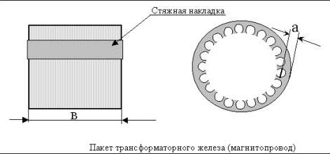
Fig. 1
Then you need to take the dimensions, as shown in Fig. 1. This blank must be soaked with liquid oil varnish. And dry using heat. This must be done so that, after removing the tie rods, the package does not crumble. As a rule, overlays from four or more pieces. On powerful electric motors, they are also electrowelded on the sides.
It is necessary to remove not only the linings, but also the boiled metal. This is done with a grinder, grinder or milling machine.
You ask: why is this done? The fact is that the magnetic flux in the future transformer will propagate differently than in an electric motor. And these pads will be short-circuited turns and, accordingly, take the lion's share of power and cause heating. And here the basic rule is the absence of short-circuited turns. They should not be, neither in the design of the transformer, nor in its fastening to the housing.
The electromagnetic parameters of such iron are most often unknown, but they can be determined experimentally with sufficient accuracy.
After you get rid of the pads and traces of electric welding, you will need to cut two end pads from cardboard or pressboard (see Fig. 2) and two cardboard sleeves. One for the outside, the other for the inside. First, end plates are installed, and then the outer and inner sleeves. Then the whole farm is wrapped with cypress, tufted or glass tape and again impregnated with varnish and dried.
Pressboard end insulator
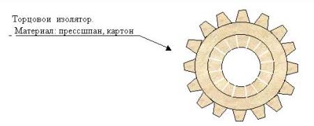
Fig. 2
Now your toroidal magnetic circuit is ready to become a real transformer. The wire will be needed in cotton or glass enamel insulation, it is possible in paper.
To continue, we need to make calculations. For the primary winding, a wire with a diameter of 2-2.5 mm is sufficient, for a secondary winding an 8 x 4 mm bus is suitable with a length of about 60 m (depending on iron). This is an option for copper. For aluminum, the cross section must be taken 15% more. Do not confuse the cross section with the diameter.
1) The number of turns per volt is made according to the formula:
48 / (a x c), where (a x c) is the area in square centimeters, not millimeters.
The voltage for the primary winding is chosen 210 V (it will sit under load). Number of turns for the primary winding:
210 x (value obtained by formula 1).
Starting from 180 V, it is necessary to make bends every 10 V: that is: 180 V, 190 V, 200 V. This is useful to you in case of low voltage in the network. For the secondary winding V = 55-65 V idling (a condition for arc stability). The turns are calculated in the same way.
If you have a stator from a 4A motor, then the coefficient of 48 can be reduced to 46.
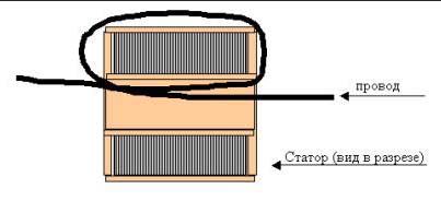
After doing the calculations, you can start winding. First primary, then secondary. It should be wound round to round, and not lined. This will give a higher inductance to the windings and optimize the operation of the transformer. You will need an assistant. Winding a tire onto a torus is a time-consuming process, especially if you don’t have a round shuttle. Therefore, the process can be simplified as follows. The bus must be launched into the torus, approximately half the length. And then wind from the middle to the end of the wire. First, one one part of the tire, then another. Otherwise, the head will spin, run back and forth. Conclusions should be fixed with a kiper tape.
Winding wire
After the winding process is completed, the transformer should be again impregnated with varnish. And dry well. Particular attention should be paid to this. It may happen that a transformer dry to the touch, when connected to the network, starts to smoke at idle. This means he came kaput. The primary winding closed. The fact is that under the influence of a strong magnetic field, some solvents (included in the composition of the varnish) begin to conduct current. Even if you have tested the varnish with a megger before use. Therefore, it is better to dry hot, in a cabinet, or apply a direct current of low voltage to the winding.
Next, assemble your transformer, as shown in the figure.I do not advise making a case out of metal, preferably plastic. Remember short-circuited turns.
Transformer assembly
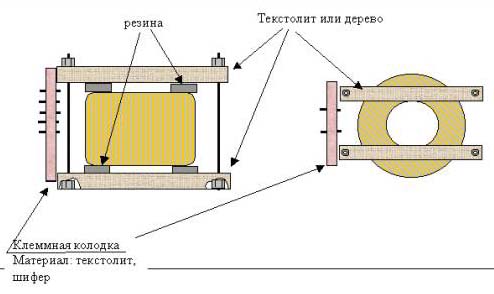
Fig. 4
If everything is done carefully, your device will cook with electrode No. 4 and cut with electrode No. 3, working from a home outlet. Traffic jams on the counter for a while should be put 16A. The device consumes about 10 A. during operation. That is, the same as a tefal teapot. On the “three” the transformer does not heat up at all, and on the “four” it is necessary to burn ten pieces continuously so that it warms up to 50 degrees. This is enough for you for the eyes, both for yourself and for the coven. If you have a five-ampere counter, then do not burn more than three or four electrodes No. 4 in a row.
I won’t talk about weight and other advantages. So much has been written about them that even fairy tales appear about miraculous properties. Better talk about where now you can get the wire for the transformer. Previously, everything was lying around in heaps of large heaps. Today the wire can be found where they work with it. We have local power grids and a locomotive depot. Double the price of this color meter twice the price of scrap metal, and a burned or punched coil from an oil transformer will always be picked up for you. In such a coil there is always a piece of a whole wire that goes into business. And if you have something in your wallet besides your own hands, then you can order it at the electrical goods store. But the cost of such a product will be several times higher than that made from scrap. Therefore, remembering the grandfather of Marx, I recommend investing at a minimum :-)). And in the midst of the sunset of life, write the book “How Steel Steal” :-))))).
See also: DIY spot welding machine
See also at bgv.electricianexp.com
: