Categories: Featured Articles » Sharing experience
Number of views: 41052
Comments on the article: 1

Connecting a three-phase motor to a household network
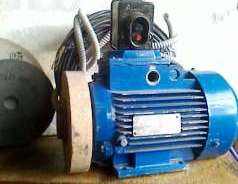
 

Connecting a three-phase motor to a household networkThe simplest and most widely used method that ensures the operation of a three-phase electric motor from a household network is to connect one of its windings through a phase-shifting capacitor.

The article discusses in detail the issues of calculating engine power and capacitance of a capacitor for various switching schemes.

To calculate the motor power and capacitance of the capacitor, the following data are needed: N - power in kilowatts, I - current in amperes, efficiency.

This data is on the tag of each engine.

Usually, two currents are given on the tag - for the star and for the triangle. You need to take a current for the star. We will extract other data from them: Na = 1000 * N / (3 * efficiency), W - the active power of the winding,

Z = U / I, ohm - impedance of the winding,

U = 220 V - voltage across the windings,

R = Na / I2, ohm - active resistance of the winding. This resistance cannot be measured by a tester and you will not see it when disassembling the engine. In explicit form, it is not. It appears only at work. By performing work, the engine consumes active energy. It is convenient to assume that this energy is released on this resistance.

ohm

- inductive resistance of the winding. It can only be calculated. DO NOT try to measure it as measured coil inductance. It in a complex way depends on the interaction of the magnetic field of the rotor with the magnetic field of the stator.

Xc is the capacitance in ohms. It is he who we will seek.

C is the capacitance of the capacitor in microfarads. We will find it from the formula C = 3183 / Xc

Nm is the power of a single-phase connection, watts.

For a numerical example, take an engine with such data. N = 3, I = 6.94, U = 220, KPD = 0.819


Connecting the motor according to the star scheme.

I will say right away that the connection according to this scheme is accompanied by the largest loss of power. Yes, only in some engines the "star" is assembled inside thoroughly. We have to put up with this reality. Maximum power is achieved with a tank with resistance -

In our example, Nm = 760.6 watts.


Connection of the engine according to the scheme "torn star 1"

The capacitor is included in the branch with one winding.

Maximum power and corresponding resistance:

Nm = 2,064 watts.

It should be noted that the current in the branch with a capacitor significantly exceeds the nominal. This can be avoided by doubling the resistance. The formulas will take the form:

Nm = 1,500 watts.

As you can see - the power drops noticeably.


Connection of the engine according to the scheme "broken star 2"

The capacitor is included in the branch with two windings. Maximum power and corresponding resistance:

Nm = 1,782 watts


Connecting the engine according to the "triangle".

Maximum power and corresponding resistance:

Nm = 2,228 watts

However, the current in the branch with a capacitor is higher than the nominal. To avoid this, you need to increase the capacitance by one and a half times. Power loss is extremely small.

Nm = 2 185 W.

Fig. 1. Schemes for connecting a three-phase motor to a household network

See also on this topic:Typical schemes for connecting a three-phase motor to a single-phase network

See also at bgv.electricianexp.com:

  • How to determine the working and starting windings of a single-phase motor
  • How to choose capacitors for connecting a single-phase and three-phase electrode ...
  • Typical schemes for connecting a three-phase motor to a single-phase network
  • Mechanical and electrical characteristics of induction motors
  • Several ways to control a single-phase asynchronous motor

  •  
     
    Comments:

    # 1 wrote: Alexander (Alex Gal) | [quote]


    Unfortunately, the article is extremely illiterate in theoretical terms.

    1. To begin with, the active power is always denoted by the Latin "P", not "N". Observing the accepted notation, you do not need to indicate "Na" - and so it will be clear that what is meant is active.

    2.To calculate the active power, you need not the efficiency of the engine, but cos phi. And if you determine not active, but useful power (from active), then you need to write this:

    Rpol = efficiency * Ra

    3.

    We will extract other data from them: Na = 1000 * N / (3 * efficiency), W - the active power of the winding,

    Not the active power of the winding, but (given the above) useful power of one phase. The winding of a three-phase motor is three-phase, so in the formula we are talking about only one phase, and not about the entire winding.

    R = Na / I2, ohm - active resistance of the winding. This resistance cannot be measured by a tester and you will not see it when disassembling the engine. In explicit form, it is not.

    I don’t know what is calculated here, because I don’t see what I2 is. It can't be active winding resistance. It is precisely the active resistance of the winding that can be easily measured by a tester. An ordinary tester does not measure the total and inductive resistance of a winding, but active resistance is easy.

    4. Actually, I just didn’t look at the formulas, because I don’t see much sense in them. They can be given much easier :). For example, for scheme No. 1 (star), the capacity selection formula looks like this:

    Slave.nom = 2800 * (Inom / U) μF

    for scheme No. 2:

    With slave.nom = 4800 * (Inom / U)

    where U is the mains voltage, in this case 220V. The same formulas exist for the remaining schemes.

    5. The article does not indicate the role of starting capacity. And sometimes it is very important if the engine starts under load or if the engine is high-speed, for example at 3000 rpm. In this case, at the time of starting up, it is necessary to connect the starting, additional capacity to the working capacity and disconnect it after the motor is untwisted. Its capacity is usually 2-3 times more than the working one.

    6. In the article about this through formulas :), a subtle hint ... and I will say for sure: in principle, precisely select the capacity for the particular engine we have chosen impossible. You can only choose the optimal capacity for some average load on the motor shaft. That is, the capacity directly depends on the load on the shaft at the moment. And if we (as in the photo) use the engine as an emery machine, we must understand that the calculated capacity will be optimal for a full load on the motor shaft, in pauses there will be almost no-load operation and increased current with overheating of the engine. I say this to the fact that the accuracy of the calculations plays a role only in the case of a constant and sufficiently large load on the engine.

    7. The article also says nothing about the choice of a switching circuit (star or triangle). And here is also the opportunity for experimentation. In principle, in order to maximize the power of a three-phase motor, you need to look at the motor plate - a diagram of its connections and voltages. If the engine is 220/380, then in a single-phase network it must be connected to the triangle. If 127/220 is indicated on the engine (there are also such ones) - then to the star. You can turn on the star and the 220/380 engine, while its power is noticeably lost, but for an initially powerful engine and a small load, the starting currents will also decrease significantly.

    Well, in the end, as usual :), I will advise a book for those who would like to understand in more detail with this question N.D. Toroptsev "Three-phase asynchronous motor in a single-phase switching circuit with a capacitor." Electrician Library Series, Issue 611, 1988 Available online in djvu.