Categories: Sharing experience, Practical Electronics
Number of views: 72039
Comments on the article: 4
PCB manufacturing using a computer
 A detailed story about the popular "laser-ironing" technology for the manufacture of printed circuit boards, its features and nuances.
Printed circuit boards in radio engineering have been used for a very long time. In production conditions, there are various equipment that allows you to produce boards on a mass scale. Such boards were previously produced by offset printing methods, which is why they were called "printed".
At home or in factory electrical laboratories involved in the repair of electrical equipment, such boards had to be painted manually with various varnishes. Tools for drawing were used in a wide variety of ways, from simply sharpened matches to needles from a syringe and glass drawing pens.
The productivity of such labor was low, and the quality left much to be desired. If it was required to make several identical boards, then the second one was drawn without much inspiration, and those following it did not add optimism.
Now computer technology has penetrated into all spheres of human activity, including amateur radio. Printed circuit boards by hand are now no longer necessary, unless very simple, which can even be cut with a knife. But first things first.
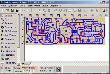
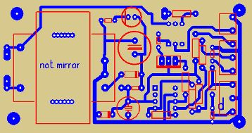
First of all, the printed circuit board must be designed according to the circuit diagram. Such work is performed on a computer using special programs. The simplest and most accessible Sprint-Layout programs. They are free and can be downloaded on the Internet. Their interface is intuitive and using the program is straightforward.
In versions of programs, starting with the third, it is possible to insert a picture and simply trace it around the lines of the printed tracks. This feature allows you to make boards published on magazine pages. A picture from a magazine, if it is simply printed, usually does not provide the required quality.
After the printed circuit board is designed and tested, it should be transferred to the blank of the future printed circuit board. And it is at this stage that care and accuracy should be shown.
First of all, it is necessary to tell how to print and on what. These are the two main questions on which the final result depends.
The board pattern is printed on a laser printer when all power-saving modes are turned off, which allows you to apply the most thick layer of toner on the paper. This helps to improve the transfer of toner to the printed circuit board blank. Now this technology is called "laser-ironing."
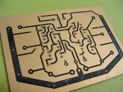
Its general meaning is quite simple: the drawing is placed on the workpiece (foil-coated fiberglass), of course, with the drawing for the foil, after which it is ironed with an ordinary iron. The toner, being melted, is transferred to the foil, leaving a board pattern on it. After that, the paper is soaked in water, and the board is etched as usual in a solution of ferric chloride.
Now about the intricacies and details of the whole process.
First of all, what to print on? When this technology was known only by rumors, it was believed that it was necessary to print the picture on the lowest quality paper. Such paper, thin and brown, was intended for typewriters. It was simply impossible to soak this paper, so it was proposed to first dissolve it, it seems, with hydrochloric acid. The paper did not dissolve well, and with it part of the pattern.
At that time, most researchers apparently printed similar pictures on state printers, so there were proposals to print even on household aluminum foil, some films, and I still don’t remember what.
In fact, everything turned out to be much simpler: coated paper from glossy magazines is best suited. At the same time, the drawings and photographs on the pages do not affect the quality.The only thing that follows empirically is to choose a magazine that gives the best quality. Some magazines are designed to such an extent that they smooth to the foil even without toner.
It is better to indicate the borders of the board on the printout with the help of “crosses,” (such an option is present in the program) than in the frame. The frame can pull the paper along during smoothing and distort the pattern.
It sometimes happens that a picture does not smooth out well the first time, therefore several copies of it must be printed on one sheet of paper. The number of drawings per sheet is set in the program.
The blank for the board should not be cut exactly in size, but so that a margin of 6 ... 10 mm remains at the edges. It is cut off after the board is ready. This is necessary so that the extreme paths of the drawing turn out well. It is not clear why, it is these tracks that smooth out poorly. Therefore, the sharp edges of the foil should be dulled by removing small chamfers.
Before smoothing the drawing with an iron, the workpiece should be cleaned with sandpaper so that the surface of the foil becomes matte. After that, degrease the surface with acetone or gasoline.
Then put the paper patterned up on a flat surface, and already on it with the foil down, orienting along the crosses, the blank of the board. To fix the blank, fold the edges of the paper inside the resulting bag. When smoothing, put the package, naturally, with the paper up.
A regular iron for ironing should be heated to 200 degrees. Temperature can be controlled using a thermocouple Avometer, or select empirically.
Smoothing should be done first with the entire plane of the iron to heat the board, and near the end of the process, smooth the paper with the edge of the iron. To prevent coated paper from sticking to the iron at the beginning of smoothing, plain plain paper can be placed under the iron. It is better to put a cardboard folder for papers or a magazine under the finished blank. This will allow the board to bend somewhat, which eliminates the influence of irregularities, both the board itself and the desktop.
After smoothing, the entire package should be cooled by applying another iron, only cold, so that the pattern is better fixed on the board.
After these procedures, smoothed paper should be soaked in warm 50 ... 60 degrees water. When the paper is sufficiently wet it should be carefully removed. Remove any remaining paper from the board by rubbing it with your finger like decals.
After a good quality impression is obtained, the blank should be etched as usual in a solution of ferric chloride. After etching, the pattern is removed with acetone or gasoline.
The Sprint-Layout program allows you to draw holes for parts in the pads. These holes should be made with a diameter of at least 0.7 ... 0.8 mm. Then the foil in them will be smoothed to the PCB and there will be no need to punch holes: the drill will center in these etched holes. The drilling accuracy is such that even microcircuits in 40 output cases “sit down” in their places without any bending of the legs.
Boris Aladyshkin
See also at bgv.electricianexp.com
:


