Categories: Featured Articles » Sharing experience
Number of views: 6488
Comments on the article: 0
Universal power supply
A universal power supply is an indispensable thing that must be present in the workshop of any radio amateur. Test the newly developed circuit, check the device that came to hand, charge the battery, urgently power up some medical device, in which the power supply unit suddenly failed or the batteries simply run out.
But you never know, it may require constant voltage. And it would be good if the value of this constant voltage could be regulated within certain limits, and even better - the presence of a current control unit in the power supply, so that when a certain current value is reached, the voltage would no longer increase, but would be kept at such a level that the in no case would the load current be exceeded.

The described needs are fully able to satisfy the laboratory power supply, which in essence is a universal power source. And not only a radio amateur, but also any home master, it is desirable to have such a universal source of electricity in the household.
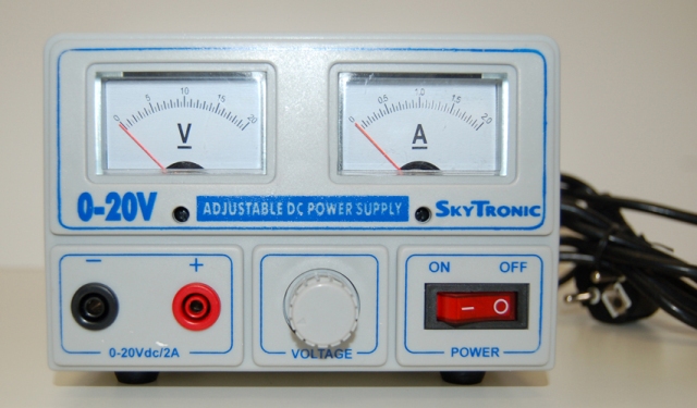
Universal laboratory units of pyatnia they are produced for various maximum current and voltage. On the front panel of such a power supply, in addition to handles for rough and precise voltage and current adjustment, there are a voltmeter and ammeter, as well as connectors for connecting probes and a button-switch. The probes and network cable are included.
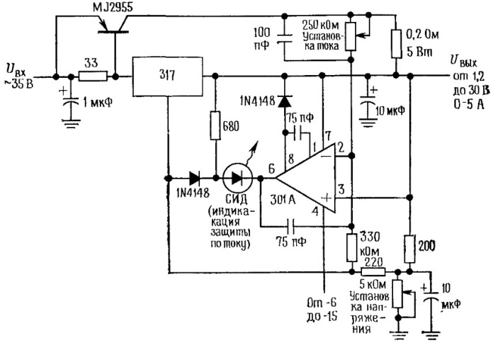
Power supplies of this kind have, as a rule, a very simple device. Let's take an example of a simplified diagram of an elementary laboratory power supply unit having the following output parameters: a constant voltage is regulated in the range from 0 to 30 V, and a current is from 0 to 5 A. A network transformer with a rectifier, as well as a voltmeter with an ammeter, are not shown in the diagram .
The initial DC voltage is obtained in such blocks, as a rule, by rectifying the alternating current, which is taken from the secondary winding of the mains transformer, is passed through diode bridge and charges the capacitor.
Further, this constant voltage, say, in the region of 35 volts, is supplied to a voltage regulator circuit made on the basis of the LM317 microcircuit - an adjustable integrated voltage regulator. This three-pin microcircuit allows you to limit the output voltage so that the voltage between its 2 and 3 pins would remain at 1.25 volts.

Since the LM317 microcircuit itself has a current limit of up to 1.5 A, the MJ2955 powerful bipolar transistor is present in the power supply circuit, and the entire operating current, up to 5 amperes, goes through it. Inside the power supply housing, this transistor is mounted on a radiator of a large area. And the LM317 chip is included in the base circuit of this powerful transistor, and only controls its current.
The output voltage is set by the regulating resistor lower in the circuit: the higher its resistance, the lower the output voltage, the base current of the MJ2955 transistor is limited by the LM317 circuit as soon as the output voltage reaches the value set by the lower resistor (see datasheet on LM317).
The operational amplifier 301A is designed here to protect the output of the power supply unit by current: when the set current is exceeded (it is set by the upper regulating resistor in the circuit), a negative voltage appears at the output of the operational amplifier, the LED LED lights up, and since the potential of the 2 output of the LM317 microcircuit is this decreases, the output voltage decreases again (by the same mechanism as the voltage limitation using the lower regulating resistor), the base current of the MJ2955 transistor is again limited by mik oskhemoy LM317.
See also on this topic:
How to make a rectifier and a simple power supply
How to make a power supply for a home laboratory
Homemade power supply for the garage
How is a computer power supply and how to turn it on without a computer
See also at bgv.electricianexp.com
:
