Categories: Featured Articles » Sharing experience
Number of views: 15371
Comments on the article: 0
How to find out the power and current of a transformer by its appearance
If there is a marking on the transformer, then the question of determining its parameters is settled by itself, you just need to drive this data into the search engine and instantly get a link to the documentation for our transformer. However, marking may not be, then we need to calculate these parameters ourselves.
To determine the rated current and power of an unknown transformer by its appearance, it is necessary first of all to understand what physical parameters of the device are determining in this context. And such parameters are primarily: the effective cross-sectional area of the magnetic circuit (core) and the cross-sectional area of the wires of the primary and secondary windings.

We will talk about single-phase transformers, the magnetic cores of which are made of transformer steel, and are designed specifically for operation from a network of 220 volts 50 Hz. So, let's say that everything is clear to us with the material of the transformer core. Moving on.

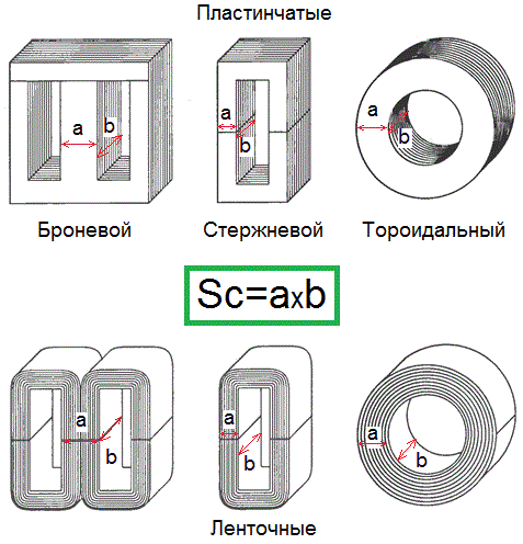
Cores come in three main forms: armored, rod, toroidal. In an armored core, the effective cross-sectional area of the magnetic core is the cross-sectional area of the central core. At the core - the cross-sectional area of the rod, because it is on it that the windings are located. For a toroidal one, the cross-sectional area of the body of the toroid (each of the turns surrounds it).
To determine the effective cross-sectional area, measure the dimensions a and b in centimeters, then multiply them - so you get the value of the area Sс in square centimeters.
The bottom line is that the magnitude of the amplitude of the magnetic flux generated by the windings depends on the effective cross-sectional area of the core. The magnetic flux Φ includes magnetic induction B as one of the factors, but magnetic induction is precisely connected with the emf in turns. That is why the working cross-sectional area of the core is so important for finding power.

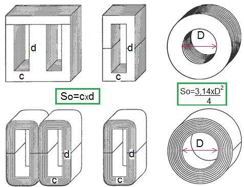
Next, you need to find the area of the core window - the place where the wires of the windings are located. Depending on the area of the window, on how tightly it is filled with conductors of the windings, on the current density in the windings, the power of the transformer will also depend.
If, for example, the window were completely filled only with the wires of the windings (this is an incredible hypothetical example), then taking an arbitrary average current density, then multiplying it by the window area, we would get the total current in the magnetic circuit window, and if we would then divide it by 2, and after - multiplied by the voltage of the primary winding - one could say that this is the power of the transformer. But such an example is incredible, so we need to operate with real values.
So, let's find the sectional area of the window.

The easiest way now to determine the approximate power of the transformer by the magnetic circuit is to multiply the effective cross-sectional area of the core and its window area (all in cm2), and then substitute them in the above formula, and then express the overall power Ptr.
In this formula: j is the current density in A / sq. Mm, f is the frequency of the current in the windings, n is the efficiency, Bm is the amplitude of the magnetic induction in the core, Kc is the fill factor of the core with steel, Km is the fill factor of the magnetic core window with copper.
But we will do it simpler: we immediately assume a frequency of 50 Hz, current density j = 3A / sq. Mm, efficiency = 0.90, maximum induction in the core - no less than 1.2 T, Km = 0.95, Ks = 0.35. Then the formula will be greatly simplified and take the following form:

If there is a need to find out the optimal current of the transformer windings, then having given the current density j, say the same 3 A per sq. Mm, you can multiply the cross-sectional area of the winding wire in square millimeters by this current density. So you get the optimal current. Or through the diameter of the wire d of the winding:

Having found out the optimal current of each winding by the cross section of the winding conductors, divide the transformer power obtained by the dimensions into each of these currents - so you will know the voltage of the windings corresponding to the found parameters.
One of these voltages will be close to 220 volts - this is with a high degree of probability and there will be a primary winding. Next, a voltmeter to help you. The transformer can be up or down, so be extremely careful and careful if you decide to include it in the network.
In addition, you may be facing an output transformer from an acoustic amplifier. These transformers are calculated a little differently than network ones, but this is a completely different and deeper story.
See also on this topic: How to determine unknown transformer parameters
See also at bgv.electricianexp.com
:
