Categories: Sharing experience, Electrician at home
Number of views: 118596
Comments on the article: 8
How to assemble and install an electrical panel with an electric meter
 In most multi-storey buildings, stairwells usually have an electrical panel, where there are meters and circuit breakers for all apartments on the site. However, in detached houses and in the old fund, electricity panels often have to be installed on their own. And given the increased power consumption in our time, the installation of an electrical panel becomes a necessity.
You can purchase an electric switchboard with a single-phase electric meter and circuit breakers, either completed already assembled or assembled in parts. Personally, I recommend the first option to you, because finding such parts so that they all fit in the shield and can be securely fixed there is not easy.
Most importantly, before purchasing an electricity meter, you should consult your local energy sales department about this. That is, in a campaign that takes money from you for consumed electricity. The fact is that electric meters can be very different, both according to the principle of action, and according to their technical characteristics. This is mainly power and accuracy class. You need to find out these data in the energy supply from the controllers, write them down, and it is also advisable to find out the address of the store where these meters are sold. Usually, energy sales workers are willing to share this data, since then they themselves will be less trouble.
After you have decided on the choice of the meter, you need to first find out in the electrics store whether there is a ready-made panel with such an electric meter and circuit breakers (“automatic machines”). If there is, then you are lucky. And if not, then you have to buy everything separately. In this case, you will need: an electric meter, a shield (a box in which the meter and "automatic machines" will fit), circuit breakers (the number is determined by the number of power lines), a bar for installing "automatic machines" (din rail), a copper contact plate for connecting 8- 10 wires and 1 meter of copper three-core cable with a cross section of at least 2.5 mm for wiring. For fastening the counter, “automatic machines” and the contact plate on the shield body, stainless (shiny) self-tapping screws with a wide hat and plastic dowels will be needed. However, some fixtures for fasteners can be provided in the shield at the factory.
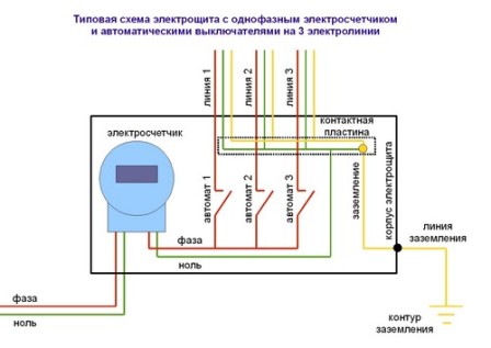
First, we evenly distribute the electric meter, “automatic machines” and the contact plate in the shield. At the same time, there should be room for holes for attaching the shield to the wall and for convenient installation of connecting wires. Then we fix the counter, din rail, plate and snap the circuit breakers to the din rail. Next, we begin to do the wiring.
We carry the phase from the meter to the "machine", designed for electric stoves. If you do not have an electric stove, then on any. To do this, we remove one core of red (brown) color from the cable, by carefully cutting its sheath. The phase from the electric meter usually comes out on the third contact on the left, but you should find out exactly about this from the instructions for the meter. We measure the desired length of the wire, given that the installation is carried out only vertically and horizontally, and not obliquely. We clean the wire into the 2 cm electric meter, insert it into the desired terminal and clamp it with bolts. For the circuit breaker, we strip the wire 1 cm and insert it into the "machine" without clamping. Now we make U-shaped jumpers from the wire, strip their ends also by 1 cm and connect the neighboring "automatic machines", now tightening the contacts on all circuit breakers. Please note that the wires in the "machines" when they are clamped should lie flat, without overlapping each other. Otherwise, over time, this connection will weaken, begin to warm up and burn.
Next, we lead zero, for which we take a wire of a different color, for example, white.We measure it from the counter to the contact plate, and the wire should also be located only vertically and horizontally. The zero terminal of the meter is usually the fourth on the left or the very first on the right, check this in the instructions for the meter. Strip and connect the neutral wire to the meter and to the contact plate.
The installation process of the electric meter is described in more detail. here.

Now you need to attach the shield to the wall. Attach the shield to the installation site and mark the places for fastening with a simple pencil (screwdriver, nail). Next, drill the wall with a 6 mm diameter drill bit to a depth of 6 cm. Insert the plastic dowels into the holes, attach the box and screw it with screws with a wide hat.
If the case of your switchboard is made of steel, then your ground (conductor from the ground loop) should go first to the case, and then to the contact plate. If the shield is plastic, then you need to make grounding directly on the contact plate.
Before connecting the meter to the power line, you need to check with your local power supply who can do this. Typically, controllers are allowed to connect the meter on their own. If not, then you must bring the power line to the meter, and the controller will connect it and seal it. In any case, stipulate all your actions on connecting the electric meter with the employees of the energy sales company (the company that takes money from you for the consumed electricity). Otherwise, you run the risk of encountering very big problems!
I remind you that no matter how experienced a person you consider yourself, it is FORBIDDEN to carry out any repair work on an existing power line without disconnecting it and checking for lack of voltage on it! To connect your switchboard to an existing power line, attract the employees of the relevant organizations for this. For an apartment building, for example, it is a housing office. And do not be shy, they are tearing up such money for servicing the housing stock, essentially not doing anything that they will gladly send you an electrician, just so that you do not resent.
See also at bgv.electricianexp.com
:
