Categories: Sharing experience, Practical Electronics
Number of views: 26810
Comments on the article: 0
Modding a computer with a beautifully illuminated analog voltmeter
How to connect an analog voltmeter to a computer and highlight it.
Nowadays, high technology can often be found voltmeters / ammeters made in the form of an LCD indicator. But all this does not look as effective as an analog retro - a voltmeter flaunting on the front panel of your case! This article provides an overview and technical performance of mods in retro style.
The voltmeter is made in a traditional style and can work well with some cases. At radio bases, one can often see not only voltmeters, but also ammeters, which can also take place on the 5’25 plug. This voltmeter is capable of measuring DC voltage from 0 to 15 volts. This is what we need, because we will use a voltmeter as a 12 volt monitoring. Let's take a closer look. The lower part of the voltmeter is covered with a plastic cap. Such a technical maneuver is only for us; under this cap you can place a backlight ...

From the side of the back wall you can see the coil and additional resistance (if you want, a resistor) ...

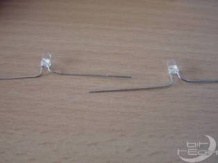
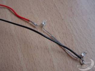
Now, after the introductory course, we will deal directly with modding. Firstly, you need to do the backlight. Our backlight will consist of two ultra-bright blue LEDs. In this case, we will use LEDs with a diameter of 3 mm, a voltage of 3.7 volts and a power of 20 mA. First, we bend the legs of the LEDs, as shown in the photo ...
Then remove our cap, which closes the bottom of the front panel. Closer to the edge, we drill holes on both sides. It will be good to drill, because plastic voltmeter ...

The next step is to process the holes in a circle so that there are no burrs and residues of drilled plastic. What to process is up to you. You can file, or you can use a knife. It turns out here are such small neat holes ...
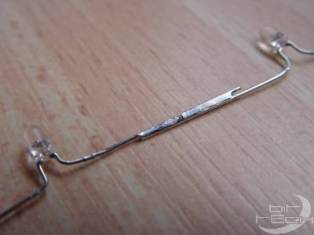
Then we sequentially solder the LEDs. Those. solder the long leg (+) of the first LED to the short leg (-) of the other LED. Caution! LEDs are very sensitive to overheating!
Solder the wires to the remaining free legs. To the short leg of the first LED - a black wire (-) ...
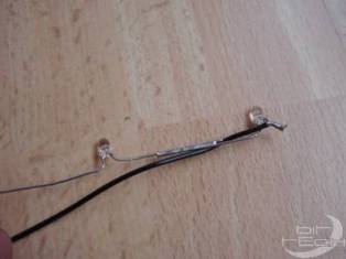
... to the long leg of the second, red (+).
Now we place all this on a voltmeter ...
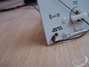
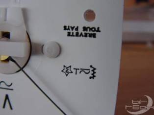
The arrow indicates the resistance that we will connect to the LEDs, because if you connect them directly to 12 Volts, then the LEDs simply burn out. You can experiment with a resistor, but I stuck 330 ohms.

All wires are soldered ... It remains only to connect 12 volts.

Start!!! Everything works! A little blue light shines, and a voltmeter shows him the set 12 Volts!

In the dark, it looks much better.

See also at bgv.electricianexp.com
: