Categories: Sharing experience, Practical Electronics, Electrician Secrets
Number of views: 243,397
Comments on the article: 5
The most common schemes for switching on single-phase and three-phase electric meters
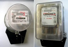 In this article we will consider the basic schemes for switching on single-phase and three-phase electric meters. I want to note right away that induction and electronic electricity meters absolutely identical.
The mounting holes for fixing both types of electric meters should also be exactly the same, however, some manufacturers do not always adhere to this requirement, therefore, sometimes there may be problems installing an electronic electric meter instead of induction in terms of mounting on the panel.
Clips for current windings of electric meters are denoted by the letters G (generator) and H (load). In this case, the generator clamp corresponds to the beginning of the winding, and the load clip corresponds to its end.
When connecting the meter, it is necessary to ensure that the current through the current windings passes from their beginnings to the ends. To do this, the wires on the side of the power source must be connected to generator clamps (terminals D) of the windings, and the wires extending from the meter to the load side must be connected to load clamps (clamps H).
For meters included with measuring transformersmust take polarity into account as current transformers (CT)so and voltage transformers (VT). This is especially important for three-phase meters with complex switching circuits, when the wrong polarity of the measuring transformers is not always immediately detected on a working meter.
If the counter is switched on via a current transformer, then a wire is connected to the beginning of the current winding from that clamp of the secondary winding of the current transformers, which is unipolar with the primary winding output connected from the power supply side. With this inclusion, the direction of the current in the current winding will be the same as with direct inclusion. For three-phase meters, the input terminals of the voltage circuits, unipolar with the generator terminals of the current windings, are indicated by the numbers 1, 2, 3. This determines the specified sequence of phases 1-2-3 when connecting the meters.
Basic schemes for switching on single-phase meters
Figure 1 shows circuit diagrams for switching on a single-phase active energy meter. The first scheme (a) - direct inclusion - is the most common. Sometimes, a single-phase electric meter is turned on semi-indirectly using a current transformer (b).
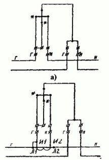
Figure 1. Schemes for switching on a single-phase active energy meter: a - for direct switching on; b - with semi-indirect inclusion. Next, we consider the inclusion of three-phase electricity meters.
The most common are direct schemes (fig. 2) and semi-indirect (fig. 3) four-wire connections:
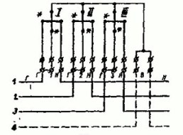
Figure 2. Scheme of direct connection of a three-phase active energy meter
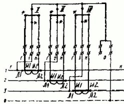
Figure 3. Scheme of the semi-indirect inclusion of a three-phase active energy meter.
With half-turn on use current transformers. The selection of current transformers is based on power consumption. The industry produces current transformers with various transformation ratios - 50/5, 100/5 .... 400/5 etc.
For more information on connecting meters in everyday life, see here: How to connect an electric meter
Basic schemes for switching on three-phase electric meters
In addition to the semi-indirect scheme, it is often applied and scheme of indirect inclusion of three-phase electric meters. In this scheme, not only current transformers are used, but also voltage transformers.
Figure 4 shows connection circuit with three single-phase voltage transformers in a three-wire network, the primary and secondary windings of which are connected to a star. In this case, the common point of the secondary windings is grounded for safety reasons. The same applies to the secondary windings of current transformers.
Here it is necessary to pay attention to the presence of a mandatory connection of the neutral conductor of the network with the zero terminal of the meter, because the absence of such a connection can cause an additional error when energy is taken into account in networks with voltage unbalance.
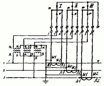
Figure 4. Scheme of indirect inclusion of a three-phase active energy meter in a three-wire network
Besides three-element three-phase electric metersuse and two-element. Schematic diagrams of the inclusion of a three-phase two-element active energy meter type SAZ (SAZU) are shown in figure 5.
Here, we especially note that the middle phase is necessarily connected to the terminal with the number 2, i.e. the phase whose current is not supplied to the meter. When you turn on the counter with voltage transformers, the clamp of this phase is grounded.
The circuit is grounded power supply side clamps (i.e. terminals I1 of current transformers), but it would be possible to ground the terminals from the load side.
SAZ type meters are mainly used with measuring transformers (NTMI), and therefore the above scheme is the main one when taking into account active energy in electric networks of 6 kV and higher.
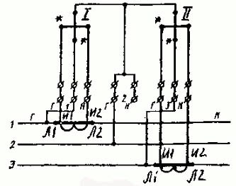
Figure 5. Scheme of semi-indirect inclusion of a three-phase two-element active energy meter in a three-wire network
It is necessary to note one point that I missed earlier. Operating voltage of induction metersincluded according to the direct and semi-indirect switching circuit is 220/380 V. In indirect switching schemes, i.e. with voltage transformers, apply electric meters for operating voltage 100 V. Some electronic electric meters have an input voltage range of 100-400 V, which theoretically allows you to use them in circuits with any type of inclusion.
When installing electricity metering according to the semi-indirect or indirect switching scheme, the correct phase rotation is very important. To determine the phase rotation, various devices are used, for example, E-117 "Phase-N".
Schemes of inclusion of reactive energy meters
Quite often, together with induction electric meters of active energy, they use reactive energy meters.
Figure 6 shows the schemes for the semi-integrated connection of meters in a four-wire network (380/220 V). This circuit requires less wire or control cable for mounting. When assembling it, the risk of incorrect switching on of the meters is significantly reduced, since the mismatch of the phases (A, B, C) of the current and voltage is eliminated.
You can check the correctness of the scheme in simplified ways without removing the vector diagram. To do this, it is sufficient to measure the phase voltages, determine the phase sequence and verify the correct inclusion of the current circuits by alternately taking the two counter elements out of operation and fixing the correct rotation of the disk.
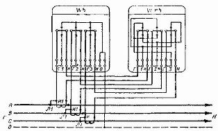
Figure 6. Scheme of the semi-indirect inclusion of three-element counters of active and reactive energy into a four-wire network with combined current and voltage circuits.
The disadvantage of this circuit is that checking the correct inclusion of current circuits makes it necessary to disconnect consumers three times and take special safety measures during work, since the secondary circuits of current transformers are under the potentials of the phases of the primary network.
Another serious drawback of this scheme is that it is necessary grounding or grounding the secondary windings of measuring transformers.
Unlike the previous circuit in Figure 7, there are separate current and voltage circuits, therefore, it allows you to check that the meters are turned on correctly and replace them without disconnecting consumers, since voltage circuits can be disconnected in this circuit. In addition, it complies with the requirements of the PUE for the grounding and grounding of the secondary windings of current transformers.
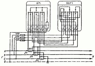
Figure 7. Scheme of the semi-indirect inclusion of three-element active and reactive energy meters in a four-wire network with separate current and voltage circuits.
And finally, consider scheme for indirect inclusion of two-element electric meters of active and reactive energy in a three-wire network over 1 kV. The schematic diagram of this inclusion is shown in Figure 8.
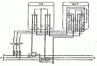
Figure 8. Scheme of indirect inclusion of two-element meters of active and reactive energy in a three-wire network over 1 kV.
In this scheme, as a reactive energy meter adopted two-element electric meter with separated serial windings. Since there is no current transformer in the middle phase of the network, instead of the current Ib, the geometric sum of the currents Ia + Ic equal to - Id is connected to the corresponding current windings of this counter.
The figure was shown switching circuit using a three-phase voltage transformer type NTMI. In practice, a three-phase voltage transformer can be used with earthing the secondary winding of phase B. Instead of a three-phase voltage transformer, two single-phase voltage transformers connected according to an open triangle circuit can also be used.
Usually, counter switching circuit usually applied to the terminal box cover. However, under operating conditions, the cover may be removed from a different type of meter. Therefore, it is always necessary to verify the reliability of the circuit by reconciling it with the typical circuit and with the marking of the clamps.
Installation of voltage circuits of the electric meter of indirect and indirect switching must be carried out in accordance with the PUE - a copper wire with a cross section of at least 1.5 mm, and current circuits - with a cross section of at least 2.5 mm.
When installing direct-connected electricity meters, installation must be performed with a wire rated for the corresponding current.
On this, the review of the switching circuits of the electric meters will be considered completed. Of course, we have considered far from all existing schemes, but only those that are most often used in practice.
Mikhail Tikhonchuk
Read also:10 advantages of electronic energy meters compared to induction
See also at bgv.electricianexp.com
:
