Categories: Featured Articles » Sharing experience
Number of views: 11530
Comments on the article: 2
How to restore technical documentation
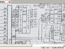 Many people who work in production, directly involved in the repair of electronic and electrical equipment, the situation is familiar, we can even say familiar and ordinary: the old equipment works, but the electrical circuits for it have already become worthless, or simply lost. Of course, there is nothing to be done in the second case, and we will consider the first case in this article.
The author of this article was prompted by the fact that he had to do a similar operation recently to restore the circuit of the electrical principle memory module of the MCTS controller. And so, what is called, in hot pursuit, until I forgot how to do it, it was decided to share with all this experience. If at least someone comes in handy, then the article can be considered useful. But, first, a little about what the MCTC controller is, because not everyone probably knows what it is.
This controller was produced by the Smolensk association "PC PROLOGUE", and was intended for the automated control of production equipment. For the eighties of the last century, this was a fairly advanced invention. The controller consisted of several modules installed on a common system crate. Depending on the complexity of the task and the number of actuators controlled by the controller, the number and composition of the modules could vary.
To enter information into the controller, discrete and analog information input modules are used, to control output devices, as a rule, relays, discrete signal output modules are used. For communication with the control computer, serial communication modules of the IPS are used.
This makes it possible to control various remote objects from a personal computer in manual (man-controlled) or automatic (computer-controlled) mode. Managed objects can be quite far from the control computer, then you have to use radio modems that are connected to the IPS modules.
The only thing you could not do without was a power supply, a central processor module, and, of course, a memory module. It is the memory module, since it contains random access memory (RAM), and read-only memory (ROM), in which the controller’s program of work is stored. The appearance of the memory module is shown in Figure 1.
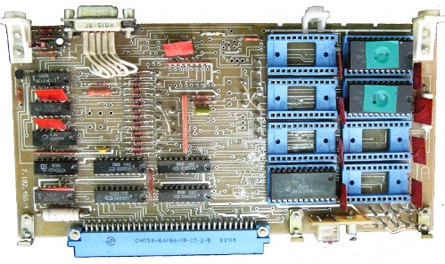
Figure 1. The appearance of the memory module
On the right side of the figure are eight blue connectors for installing memory chips, each with a volume of 2K. It should be noted that 1K is 1024 bytes, not exactly 1000, although they very often say “One kilobyte”, and then they wonder why this flash drive is slightly smaller than the 8GB declared on it. It is here that these 1024 make themselves known!
On the left side of the board are 9 K555 series chipsthat manage memory chips (drives) and communicate with the processor system interface. The module is connected to the system interface using a 64-pin connector type SNP 58. In Figure 2, this connector is shown separately, larger. Four ellipses are circled in red, we must assume the release date of this particular connector, and most likely the module itself.

Figure 2
Pay attention to the release date! 92 year, however. But even such museum exhibits still continue to work, and probably not only where the author of this article works. It is disgusting that such junk still works, no. The worst thing is that it has to be repaired, for which it is necessary to look at the circuit diagrams, which, to put it mildly, have faded somewhat, and it is very difficult to make out anything on them.
Despite the fact that there were a lot of these modules, there was only one single copy of the circuit, and that one of 1999.It should be noted here that this equipment is used in a water supply automation system, where the chlorine atmosphere is everywhere. In this atmosphere, everything rusts, even stainless steel. What can we say about some piece of paper with a diagram? That's right, she is poor, completely out of commission: the paper turned yellow, and the scheme, to put it mildly, faded.
Someone might say: “What is he writing here? It is enough just to pass the circuit through the scanner, correct it a bit in Photoshop and ... ". Let me report that everything is somewhat different. The scheme is so “vaporized” that when scanning even in the “text” mode, it turns out just a clean white sheet, at best with obscure points.
Therefore, I had to scan the circuit in Black and White. Grayscale ”, choosing the brightness and contrast of the image. The result is almost what I wanted, you can even print it on paper. But then look at the little black letters on a gray background, you see, somehow it’s not very comfortable.
Here, the article cannot insert a fully scanned document, so you will have to bring individual fragments, just like screenshots. Figure 3 shows a fragment of a scanned diagram. The horizontal black stripe on the scan is a trace of the fold of a paper sheet, since the scheme was embedded in a booklet.
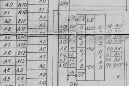
Figure 3
Consider, in principle, everything is possible, but I would like better. To black letters and lines were on a white background. How to do this?
You can try to do something in Photoshop, but it is too difficult and long. You can turn to sPlan_7 program, which allows you to simply circle the pasted drawings, approximately like this, as shown below in Figure 4.
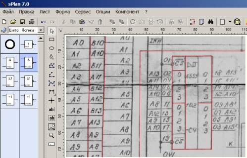
Figure 4
Everything is quite simple. We insert the picture into the sPlan program window, after which we circle the diagram with lines. To facilitate the task in the stroke process, it is better to make the color of the lines different, even red. After the entire circuit is circled, the most crucial moment comes, namely, the introduction of numbers and letters, which is very painstaking and long. More details about working in the sPlan program are described in the article “How to draw a diagram of an electric lighter in sPlan 7.0 program”.
It’s much faster and easier to bring the scanned document to the desired form if you convert it to * .djvu format, which can be done using the DjVu Solo 3.1 program, which allows you to not only view ready-made deja vu files, but also create your own from drawings in various graphic formats . The program is free, like any of the djvu viewers. How to use it is shown in the pictures below.
Run the program and click File-Open, as shown in Figure 5.
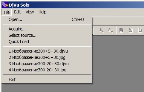
Figure 5
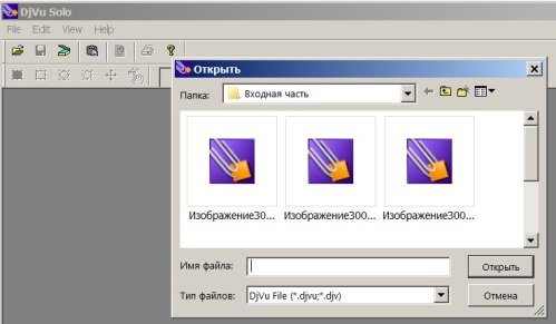
Fig. 6.
The program offers to insert files in deja vu format, as shown in Figure 6. But I would like to insert * .jpg, * .png or something else.
To do this, click on the triangle in the right part of the “File Type” drop-down list, as in Figure 7.
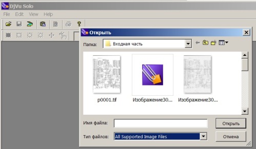
Figure 7
You can select all supported graphic program files, even * .tif. We select one of the most successful scans and paste it into the program, as shown in Figure 8.
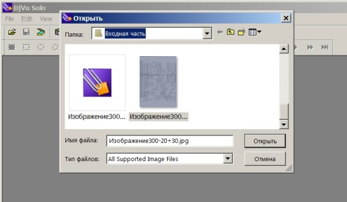
Figure 8
The selected file is called “Image 300-20 + 30”. The numbers in this entry indicate that the scan resolution is 300 dpi, the brightness is -20, the contrast is +30. This is so, for information, to determine which of the scans will be better. After the file for conversion is selected, the next picture shown in Figure 9 will appear in the DjVu Solo 3.1 program window.
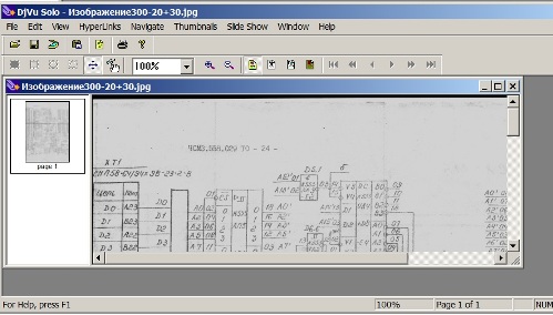
Figure 9
Next, in the File menu, select Encode As DjVu (encode in deja vu), as shown in Figure 10.
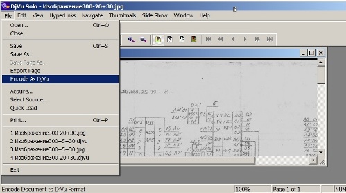
Figure 10
After clicking Encode As DjVu, a file in the deja vu format appears in the folder with the source images, which is proposed to be saved, as shown in Figure 11.
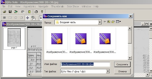
Figure 11.
It is proposed to save the picture with the same name as the original picture, only with the * .DjVu extension. But, of course, when saving, you can specify any name that seems more convenient for further use.
In the left part of the window you can see a small rectangle with the inscription page1 below it.This suggests that for encoding in * .DjVu format, only one page in * .jpg format was inserted into the program, resulting in a * .DjVu file consisting of only one page.
If you insert several graphic files into this field, then the * .DjVu file will contain several pages - you get a whole book. But we are still interested in the file “Image 300-20 + 30.djvu”, which contains only one page. Double-clicking on this file opens it in the DjVu viewer. A fragment of an open file is shown in Figure 12.
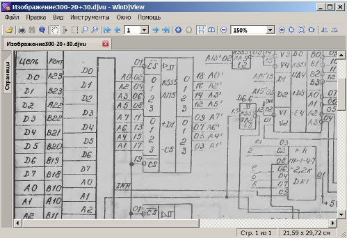
Figure 12.
It is easy to see that, compared with the scanned image of gray, as if nothing had changed. Then why was all this done? Just another operation has not been done, quite simple, for which all this was carried out. If you open this file in black and white, then everything will become clear. To do this, select black-and-white mode from the viewer menu, as shown in Figure 13.
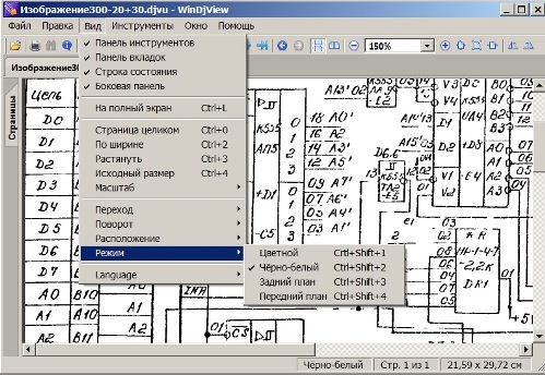
Figure 13.
It is easy to see that some lines turned out to be broken. If this quality suits you, then you can simply print the resulting image as is.
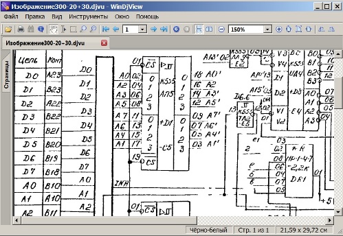
Figure 14.
If you still want to slightly improve the image quality, then the easiest way to do this is to convert the image to * .png format. To do this, open the file in the DjVu viewer and right-click on the resulting image, as shown in Figure 15.
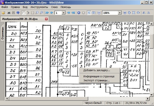
Figure 15.
Then, in the drop-down menu, left-click on the item “Export Page ...”, as a result of which it will be offered to save the selected image with the name p0001.png. The file name, of course, can be changed if it is more convenient, but for now, let's leave this name, since there is only one page.
This may raise the question, why do this export? Everything is very simple: open the p0001.png file in the Paint system program, and use the Line tool to paint over the "pockmarked" lines, and where you want to erase the excess with the eraser. A fragment of the circuit corrected in the Paint program is shown in Figure 16.
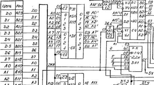
Figure 16.
Such retouching in the Paint system program is much simpler and faster than in Photoshop or in the sPlan_7 program, while the quality of the circuit is quite high.
Boris Aladyshkin
See also at bgv.electricianexp.com
:
