Categories: Sharing experience, Practical Electronics
Number of views: 136846
Comments on the article: 14
LED Lamp Repair - Replacing a LED in a failed lamp
Is it possible to repair purchased LED lamps? This question, given the high cost of the lamps, is quite relevant, a lot has already been written on this topic in Internet forums. The most frequently discussed issues are the repair of lamps purchased at Aliexpress.
In the article “Shopping on Aliexpress is a personal shopping experience in a Chinese online store” among other things, it was told about the purchase of LED lamps, so popular recently. Actually, the article began with these lamps: the quality of these lamps left much to be desired, mostly attracted by the low price. But in some places where too much light is not required, these lamps came in handy.
Further exploitation revealed that these lamps are not as durable as promised in the advertisement. If the lamps of the “Navigator” trademark have been working with the author of the article for almost two years already, then the lamps purchased at “Aliexpress” fail in a month - another, or even earlier. The case is indicative when the lamp replaced in the evening, the next day, just did not turn on. As a result, two faulty identical lamps.
Someone else would have simply thrown out an unusable lamp, but not a radio amateur. Therefore, radio amateurs, first try to find out the scale of the disaster, and, if possible, eliminate the defect. So it was this time. Not that Chinese lamps are too expensive, but if you can restore it, you won’t have to buy another lamp. As they say, the savings are obvious.
The appearance of these lamps is shown in the figure.
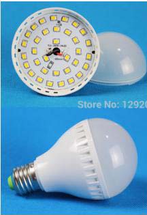
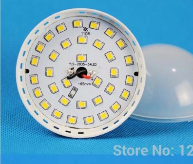
This picture is taken from the site "Aliexpress". Apparently, sellers assumed that someone would disassemble and repair such lamps, and, repair, as they say, is just around the corner. A larger board is shown in the figure below. From the inscription on the board it is easy to understand that the lamp is assembled from 34 LEDs of the standard size SMD2835 (2.8 * 3.5 mm).
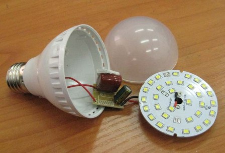
Disassembling the lamp showed that there is a small power supply board inside. Only visible in the photo capacitors, all other parts are SMD-mounted and are located on the back of the board.
The circuit assembled on the board is shown in the figure below. It’s impossible to come up with a simpler: a conventional transformerless power supply with a quenching capacitor.
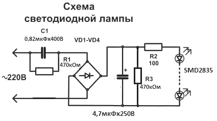
The purpose of the parts is clear: resistors R1, R3 discharge capacitors after disconnecting from the network. This is done so as not to pinch with current when touching these capacitors with your hands. With regard to capacitor C1, everything is clear. If you turn the lamp out of the holder, then touching the base may not be very pleasant. It all depends on what charge will remain on capacitor C1.
The charge on the electrolytic capacitor can remain only if at least one LED breaks. This charge can be "felt" only by disassembling the lamp. Although the resistor R3 has another purpose.
In the event of a blown LED circuit (at least one LED), the voltage on the electrolytic capacitor remains at a level not exceeding the operating voltage of the electrolytic capacitor.
In the diagram, the working voltage of the electrolyte is 250V. If we assume that the voltage drop on one LED is 3V, then 34 * 3 = 102V will drop on 34 LEDs. It turns out something like a parametric voltage regulator. Therefore, 250V is theoretically more than enough.
Apparently, the Chinese developers reasoned in a similar way: there are lamps in which the operating voltage of the electrolytic capacitor is only 100V. Basically, these are small-sized lamps with a power of 3 ... 5W, where it is difficult to hide a high-voltage capacitor. In the lamp shown in the photo, the operating voltage of the electrolytic capacitor is 400V.But the resistor R3, most likely, will not be superfluous.
Resistor R2 is designed to limit the current through the LEDs. But this is only in the diagram. In fact, on the circuit board inside the lamp, it simply does not exist. The function of limiting the current through the LED circuit is successfully performed by the capacitor C1. This is an option scheme. Maybe other manufacturers still put this resistor.
So, as it was written just above, two faulty lamps were immediately available, each of them had just one LED. Moreover, there were no visible defects in the form of soot on the board, there was no destruction or blackening of the LED itself. Therefore faulty Light-emitting diode had to find. To do this is quite simple: with digital multimeter LEDs are dimly lit. Naturally, if the multimeter probes are connected in the forward direction.
It was decided to put one lamp on spare parts, remove the LED from it and solder to another. Attempts to solder the LED using a hot air gun were unsuccessful: the LED did not want to be soldered.
The fact is that there is an aluminum radiator on the reverse side of the printed circuit board, because LEDs, like all semiconductor devices, really do not like high temperature. But even without a radiator, the process of soldering parts from a printed circuit board is much more complicated and dramatic than soldering new parts onto a board.
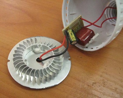
Repair should start by searching for a faulty LED if the lamp goes out completely and immediately. If the lamp starts to blink, or just lights dimly, then the fault lies in the power supply. Most often this happens due to a malfunction of capacitor C1.
The easiest repair option is to replace the known capacitor C1. A faulty electrolytic capacitor can almost always be detected by eye on a swollen bottom. This is how modern explosion-proof electrolytes behave.
After detecting a faulty LED, it is easiest to unsolder it as follows. The first thing to do is remove the yellow elastic filter with a thin screwdriver or needle. Under it will be a metal surface with a crystal. On this surface put a piece of solder and a small amount of gel-like flux. Warm up this “sandwich” with a well-heated soldering iron with a power of at least 60 ... 80 W until the LED comes off the board.
Some better results can be achieved if, instead of solder, a low-melting alloy, for example, Wood's alloy, is put. Such an alloy in the form of small cakes is sold on radio markets. Mixing with the main solder, usually lead free, Wood's alloy lowers the melting point of the lead free solder. Therefore, the soldering process becomes easier and faster, the likelihood of overheating the circuit board is significantly reduced.
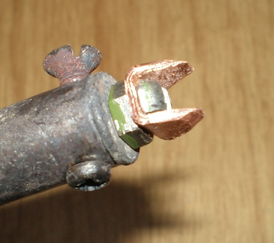
Another way to unsolder a faulty LED is a thermal tweezers. But not everyone has this tool, and it’s hardly worth buying it for a single use. Therefore, it is better to make a U-shaped sting, or use the homemade sting shown in the figure below.
After the faulty LED is sealed off, it remains to replace it with a new one. LEDs of sizes 2835 or 5730 can be ordered in the same place where the lamps were purchased, on Aliexpress. They stand there quite inexpensively, about 50 rubles per hundred pieces.

Judging by the price, these are not the best LEDs, but the lamps were nevertheless repaired, and the glow of these LEDs is no worse than those that were originally.
Soldering a new LED to the board is not difficult. This can be done with a regular soldering iron. The remnants of the old lead-free solder should be removed from the board. This is best done using a wire braid from a shielded wire.
The braid must be impregnated with flux, in the simplest case, rosin. Then, with a well-heated soldering iron through the braid, pass along the contact pads, the solder is absorbed into the braid. After that, irradiate the board contacts with POS 61 solder or the like.
Now it remains only to solder the LED installed on the pads. It is imperative that the LED contacts be coated with a flux layer, preferably gel-like. After that, it is enough to touch the ends of the LED with a soldering iron to melt the solder remaining on the board contacts. Soldering is so fast that the finger holding the LED on the board does not feel any temperature increase.
Boris Aladyshkin
See also at bgv.electricianexp.com
:
