Categories: Sources of light, How does it work
Number of views: 18479
Comments on the article: 1
How electronic ballasts are arranged and work for fluorescent lamps
Fluorescent lamps cannot work directly from a 220V network. To ignite them, you need to create a high voltage pulse, and before that heat their spirals. To do this, use ballasts. They are of two types - electromagnetic and electronic. In this article we will consider electronic ballasts for fluorescent lamps, what is who and how they work.
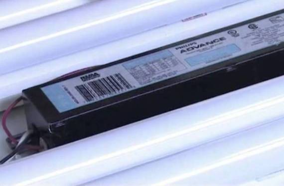
What does a fluorescent lamp consist of and why is ballast needed?
Fluorescent lamp is this gas-discharge light source. It consists of a tube-shaped flask filled with mercury vapor. At the edges of the flask are spirals. Accordingly, on each edge of the flask is a pair of contacts - these are the conclusions of the spiral.
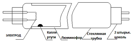
The operation of such a lamp is based on the luminescence of gases when an electric current flows through it. But the current just between the two metal spirals (electrodes) just does not flow. For this, a discharge must occur between them, this discharge is called smoldering. For this, the spirals are first heated up by passing current through them, and then a high voltage pulse of 600 volts or more is applied between them. Heated spirals begin to emit electrons and under the action of high voltage a discharge is formed.
If you do not go into details, then the description of the process is enough to formulate the problem for the power source of such lamps, it should:
1. Preheat the spiral;
2. Form an ignition pulse;
3. Maintain voltage and current at a sufficient level for lamp operation.
Interesting: Compact fluorescent lamps, which are often called "energy-saving", have a similar structure and requirements for their operation. The only difference is that their dimensions are significantly reduced due to the special shape, in fact this is the same tubular flask, the shape is not linear, but twisted into a spiral.
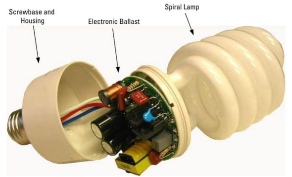
A device for powering fluorescent lamps is called a ballast (abbreviated ballast), and among the people simply - ballast.
There are two types of ballast:
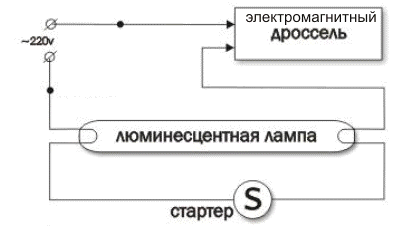
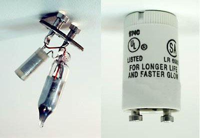
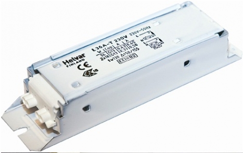
1. Electromagnetic (EmPRA) - consists of a throttle and a starter. Its advantages are simplicity, and there are many disadvantages: low efficiency, ripple of the light flux, interference in the power supply network during its operation, low power factor, buzz, stroboscopic effect. Below you see its diagram and appearance.
2. Electronic (electronic ballasts) - a modern power source for fluorescent lamps, it is a board on which a high-frequency converter is located. It is deprived of all the above disadvantages, due to which the lamps give a greater luminous flux and service life.
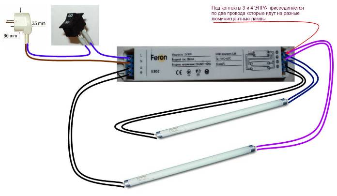
Electronic ballast circuit
A typical electronic ballast consists of the following units:
1. The diode bridge.
2. A high-frequency generator made on a PWM controller (in expensive models) or on a car-generator circuit with a half-bridge (most often) converter.
3. Starting threshold element (usually a DB3 dinistor with a threshold voltage of 30V).
4. Kindle power LC circuit.
A typical diagram is shown below, we will consider each of its nodes:
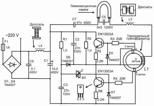
Alternating voltage is supplied to the diode bridge, where it is rectified and smoothed by a filtering capacitor. In the normal case, a fuse and an EMI filter are installed before the bridge. But in most Chinese electronic ballasts there are no filters, and the capacity of the smoothing capacitor is lower than necessary, which causes problems with ignition and operation of the lamp.
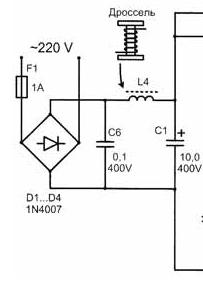
Tip: if you are repairing electronic ballasts, then read the article "How to check the diode bridge" on our website.
After that, the voltage goes to the oscillator. From the name it is clear that the oscillator is a circuit that independently generates oscillations.In this case, it is made on one or two transistors, depending on the power. Transistors are connected to a transformer with three windings. Commonly used transistors are MJE 13003 or MJE 13001 and the like, depending on the power of the lamp.
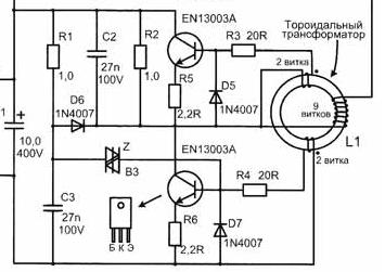
Although this element is called a transformer, it does not look familiar - it is a ferrite ring on which three windings are wound, several turns each. Two of them are managers, each with two turns, and one is a working one with 9 turns. The control windings create pulses on and off transistors, connected at one end to their bases.
Since they are wound in antiphase (the beginning of the windings are marked with dots, pay attention to the diagram), the control pulses are opposite to each other. Therefore, the transistors open in turn, because if you open them at the same time, then they simply closed the output of the diode bridge and any of this burns out. One end of the working winding is connected to the point between the transistors, and the other to the working inductor and capacitor, through which the lamp is powered.
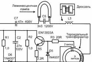
When current flows in one of the windings in the other two, an EMF of the corresponding polarity is induced, which leads to transistor switching. The oscillator is tuned to a frequency above the sound range, that is, above 20 kHz. It is this element that is a direct current to alternating frequency converter.
A dinistor is installed to start the generator, it turns on the circuit after the voltage on it reaches a certain value. A DB3 dinistor is usually installed, which opens in the voltage range of about 30V. The time after which it opens is set by the RC circuit.
Retreat:
More advanced versions of electronic ballasts are built not on a self-generating circuit, but on the basis of PWM controllers. They have more stable characteristics. However, for more than five years of studying electronics, I have never come across such an electronic ballast, all of which I worked with were auto-generating.
The LC chain has been repeatedly mentioned above. This is a throttle mounted in series with the spiral, and a capacitor mounted parallel to the lamp. First, a current flows through this circuit, heating the spirals, and then a high voltage pulse is formed on the capacitor igniting it. The throttle is performed on a W-shaped ferrite core.
These elements are selected so that at the operating frequency they enter the resonance. Since the inductor and capacitor are installed in series at this frequency, voltage resonance is observed.
Reference:
With the resonance of the voltages at the inductance and capacitance, the voltage in idealized theoretical examples begins to increase significantly to an infinitely large value, while the current is consumed extremely small.
As a result, we have a frequency generator and a resonant circuit. Due to the increase in voltage across the capacitor, the lamp ignites.
Below is another version of the scheme, as you can see - everything is basically the same.
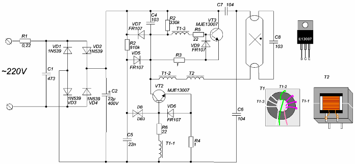
Due to the high operating frequency, it is possible to achieve small dimensions of the transformer and inductor.
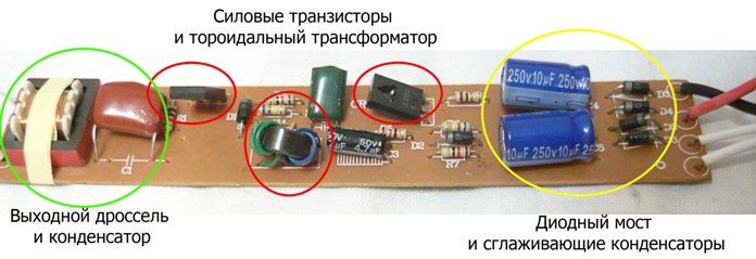
To consolidate the information passed, we consider the real electronic ballast board, the main nodes described above are highlighted in the picture:
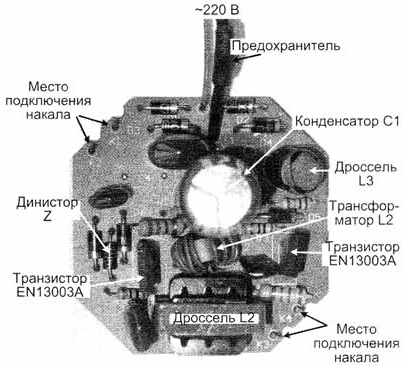
And this is a board from an energy-saving lamp:
Conclusion
Electronic ballast significantly improves the lamp firing process and works without ripple and noise. Its circuit is not very complex and on its basis you can build a low-power power supply. Therefore, electronic ballasts from burned-out energy savers are an excellent source of free radio components.
Fluorescent lamps with an electromagnetic ballast are not allowed to be used in industrial and domestic premises. The fact is that they have strong pulsations, and a stroboscopic effect may occur, that is, if they are installed in a turning workshop, then at a certain speed of the spindle of the lathe and other equipment, it may seem to you that it is stationary, which can cause injuries . With electronic ballast this will not happen.
See also at bgv.electricianexp.com
:
