Categories: Interesting Facts, Auto electrician
Number of views: 31242
Comments on the article: 0
Recovery of electric energy and its use
 The traditional way to get rid of excess energy released in frequency converters during braking of the asynchronous motors controlled by them, it was dissipated in the form of heat on the resistors. Braking resistors were used wherever there was a high inertia of the load, for example, in centrifuges, on electric vehicles, on load stands, etc.
Such a solution was necessary in order to limit the maximum voltage at the terminals of the converters in braking mode. Otherwise, the frequency converters would fail, because it would be impossible to control the parameters of acceleration and braking.
Braking resistors did not burden the equipment economically, but some inconveniences invariably entailed. Resistors are dimensional, they are very hot, they need protection against moisture and dust. And all this is connected only with the fact that it is necessary to dissipate wasted energy, for which the enterprise pays money, and the money is not small, especially if we are talking about large-scale production.
In the summer, additional heating of the surrounding air is especially undesirable, because the technological equipment is already heated with warm air, and then there are also resistors heated to 100 degrees and above. Need additional ventilation - again costs.
But there is another way. Why dissipate energy in vain? You can return it to the network back, and so save energy. Then they come to the rescue energy recovery systems.
Of course, today's frequency converters greatly reduce the consumption of electricity by equipment, due to the optimization of the power supply method of engines of various technological equipment, and this saves resources. But the use of recuperation further increases the savings. Energy may not be dissipated by resistors during braking, but may be returned to the network taking into account the current network parameters.
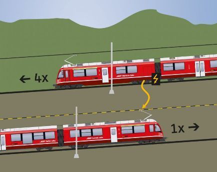
Today, leading manufacturers of industrial machinery and equipment are already implementing such systems on electric vehicles: for trolley buses, electric trains, escalators, trams, and finally - for electric cars.
How does the recovery system work? An alternating current source supplying a motor or other installation must be able to take energy back. For this, instead of a conventional rectifier, a pulse-width modulated converter is used. Such a converter is able to direct power flows both from a source to a consumer, and from a consumer to a source. This way allows you to bring the power factor to unity.
A typical IGBT cascade of the frequency converter operating in the recovery mode is initially presented as a sinusoidal current rectifier, but when braking it generates a pulse-width modulated signal, in which the direction of the current, when the voltage at the terminals is above a certain level, is not directed from the network, and to the network from the consumer circuit.
The voltage difference between the supply network and the load circuit is applied to the recovery inductor. Inductance blocks high-frequency harmonics, and an almost pure sinusoidal current is obtained, there is no need for synchronizing equipment, it is enough to apply three test pulses from the PWM modulator to the network to determine the frequency and phase of the voltage at the current moment.
An example is the frequency converters with a recovery system from Control Techniques, which are used, in particular, at the Lamborghini and Nissan factories to power dynamic test benches, as well as on escalators and various metallurgical solutions.
The essence is the same everywhere - a bi-directional energy flow is created both to the consumer from the network, from the source, and from the consumer to the network. When designing recovery systems, a number of factors are taken into account: the range of mains voltage, equipment rating and power factor, maximum power taking into account overload, level of losses.
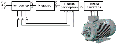
The diagram shown in the figure shows a single-engine solution, where the engine drive and the heat exchanger drive are each in one copy, their values are equal. But sometimes motor overloads occur, and then a more powerful recovery drive is required in order to cover the lower voltage limit and motor losses.
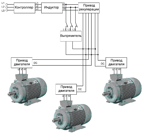
The same principle ensures the operation of several engines with several motor drives, while putting one powerful recovery drive that can pass through the total power for all engines of the system, taking into account the possibility of simultaneous braking of all engines.
To limit the starting current in systems with several motors, when the DC buses are combined, thyristor modules are used, connected by contactors to DC-charged capacitors of the converter. After charging the capacitors, the thyristor module is turned off. Obviously, recovery systems are configured differently and are designed individually.
Speaking about recovery, one can not help but recall the regenerative braking systems used in modern hybrid car engines, where the basis is the path of electrical recovery of kinetic energy.
Whenever a car moves, kinetic energy is manifested. But when braking in the traditional way, excess energy is simply lost in the form of heat, brake pads rub against brake discs, wasting kinetic energy in vain, heating friction material and metal, ultimately losing heat to the surrounding air. This is a very wasteful approach.
The regenerative braking system does not consume kinetic energy simply by friction in order to brake. Instead, an electric motor included in the transmission is used, which starts to act as a generator during braking, converting the torque on the shaft to electricity charging the battery, and the braking torque of the rotor arising in the generator mode gives the car the desired braking. The energy stored in the battery in this way after some time again serves to move the car, that is, it is reused.
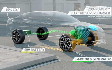
Regenerative braking allows you to maximize the use of the available resource of each battery charge, and fuel is greatly saved. Since when braking, 70% of the kinetic energy is on the front axle, the recovery system is mounted on the front axle in order to more efficiently save energy.
The greatest efficiency of regenerative braking is achieved at high speeds, and at low speeds, the efficiency of the system decreases. For this reason, along with regenerative braking, one way or another, a friction brake system is present. The joint work of the two systems is provided by an electronic controller.
The controller implements a number of functions: it controls the speed of rotation of the wheels, maintains the correct braking torque, distributes the braking force between the recovery and friction brakes, and maintains a torque that is acceptable for an optimal battery charge.
Of course, there is no direct mechanical connection between the brake pedal and the friction pads in such vehicles. The electronic unit ensures the correct interaction of the ABS, the system of exchange rate stability, the brake force distribution system and the emergency brake booster.
See also at bgv.electricianexp.com
:

