Categories: Featured Articles » Interesting Facts
Number of views: 15868
Comments on the article: 0
Peltier thermoelectric module - device, principle of operation, characteristics
The phenomenon of the emergence of thermo-EMF was discovered by the German physicist Thomas Johann Seebeck back in 1821. And this phenomenon consists in the fact that in a closed electric circuit consisting of heterogeneous conductors connected in series, provided that their contacts are at different temperatures, an EMF occurs.
This effect, named after its discoverer, the Seebeck effect, is now simply called thermoelectric effect.

If the circuit consists of only a pair of dissimilar conductors, then such a circuit is called thermocouple. In a first approximation, it can be argued that the magnitude of the thermo-emf depends only on the material of the conductors and on the temperatures of the cold and hot contacts. Thus, in a small temperature range, thermo-EMF is proportional to the temperature difference between cold and hot contacts, and the proportionality coefficient in the formula is called the thermo-EMF coefficient.
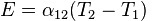
So, for example, at a temperature difference of 100 ° C, at a cold contact temperature of 0 ° C, a pair of copper-constantan has a thermo-EMF of 4.25 mV.
Meanwhile The thermoelectric effect is based on three components:
The first factor is the difference in different substances in the dependence of the average electron energy on temperature. As a result, if the temperature of the conductor is heated at one end, the electrons acquire higher speeds there than the electrons at the cold end of the conductor.
By the way, the concentration of conduction electrons also increases in semiconductors with heating. Electrons rush to the cold end at a high speed, and a negative charge accumulates there, and an uncompensated positive charge is obtained at the hot end. So there is a component of thermo-EMF, called volumetric EMF.
The second factor is that for different substances, the contact potential difference depends on the temperature differently. This is due to the difference in the Fermi energy of each of the conductors brought into contact. The contact potential difference arising in this case is proportional to the Fermi energy difference.
An electric field is obtained in a thin contact layer, and the potential difference on each side (for each of the conductors brought into contact) will be the same, and when the circuit is circled in a closed circuit, the resulting electric field will be zero.
But if the temperature of one of the conductors differs from the temperature of the other, then due to the dependence of the Fermi energy on temperature, the potential difference will also change. As a result, there will be contact EMF - the second component of thermo-EMF.
The third factor is the phonon increase in EMF. Provided that there is a temperature gradient in the solid, the number of phonons (phonon - the quantum of vibrational motion of crystal atoms) moving in the direction from the hot end to the cold will prevail, as a result of which together with phonons a large number of electrons will be carried away towards the cold end , and a negative charge will accumulate there until the process comes to equilibrium.
This gives the third component of thermo-EMF, which at low temperatures can be hundreds of times higher than the two components mentioned above.

In 1834, the French physicist Jean Charles Peltier discovered the opposite effect. He found that when an electric current passes through a junction of two dissimilar conductors, heat is released or absorbed.

The amount of heat absorbed or released is associated with the type of soldered substances, as well as with the direction and magnitude of the electric current flowing through the junction.The Peltier coefficient in the formula is numerically equal to the coefficient of thermo-EMF multiplied by the absolute temperature. This phenomenon is now known as peltier effect.
In 1838, the Russian physicist Emiliy Khristianovich Lenz understood the essence of the Peltier effect. He experimentally tested the Peltier effect by placing a drop of water in the junction of antimony and bismuth samples. When Lenz passed an electric current through the circuit, the water turned into ice, but when the scientist reversed the direction of the current, the ice quickly melted.
The scientist established in such a way that when the current flows, not only Joule heat was released, but also the absorption or release of additional heat occurred. This additional heat was called Peltier heat.

The physical basis of the Peltier effect is as follows. The contact field at the junction of two substances, created by the contact potential difference, either prevents the passage of current through the circuit, or contributes to it.
If the current is passed against the field, then the work of the source is required, which should spend energy on overcoming the contact field, as a result of which the junction is heated. If the current is directed so that the contact field supports it, then the contact field does the work, and the energy is taken away from the substance itself, and not consumed by the current source. As a result, the substance in the junction is cooled.
The most expressive Peltier effect in semiconductors, due to which Peltier modules or thermoelectric converters.

At the heart of Peltier element two semiconductors in contact with each other. These semiconductors are distinguished by the energy of electrons in the conduction band, so when a current flows through the point of contact, the electrons are forced to acquire energy in order to be able to transfer to another conduction band.
So, when moving to a higher-energy conduction band of another semiconductor, the electrons absorb energy, cooling the transition site. In the opposite direction of the current, the electrons give off energy, and heating occurs in addition to the Joule heat.

Peltier semiconductor module consists of several pairs semiconductors p and n-typeshaped like small parallelepipeds. Usually, bismuth telluride and a solid solution of silicon and germanium are used as semiconductors. Semiconductor parallelepipeds are interconnected in pairs by copper jumpers. These jumpers serve as contacts for heat exchange with ceramic plates.
Jumpers are located so that on one side of the module there are only jumpers providing an n-p transition, and on the other hand, only jumpers providing a p-n transition. As a result, when a current is applied, one side of the module heats up, the other side cools, and if the polarity of the supply is reversed, the heating and cooling sides will change places accordingly. Thus, with the passage of current, heat is transferred from one side of the module to the other, and a temperature difference occurs.

If now one side of the Peltier module is heated and the other is cooled, then thermo-emf will appear in the circuit, that is, the Seebeck effect will be realized. Obviously, the Seebeck effect (thermoelectric effect) and the Peltier effect are two sides of the same coin.
Today you can easily purchase Peltier modules at a relatively affordable price. The most popular Perrier modules are TEC1-12706 type, containing 127 thermocouples, and designed for 12 volt supply.
With a maximum consumption of 6 amperes, a temperature difference of 60 ° C is achievable, while the safe operating temperature range declared by the manufacturer is from -30 ° C to + 70 ° C. The size of the module is 40mm x 40mm x 4mm. The module can work both in cooling-heating mode and in generation mode.

There are more powerful Peltier modules, for example TEC1-12715, rated at 165 watts. When powered by a voltage from 0 to 15.2 volts, with a current strength of 0 to 15 amperes, this module is able to develop a temperature difference of 70 degrees.The size of the module is also 40mm x 40mm x 4mm, however, the range of safe working temperatures is wider - from -40 ° C to + 90 ° C.
The table below shows the data on Peltier modules that are widely available on the market today:
See also at bgv.electricianexp.com
: