Categories: Featured Articles » Autonomous power supply
Number of views: 10662
Comments on the article: 0
Solar Connection Diagram
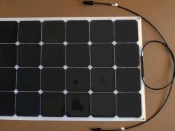 Connecting solar panels should not be difficult. There is nothing extraordinary in this procedure. But as I continue to get questions on the scheme of connecting solar panels, I decided to write this article and give illustrations to remove these issues once and for all.
From the physics of the school period, we know the concepts of series, parallel and series-parallel (or mixed) connections. There is nothing in solar panels that would bring their connection beyond the concepts of school physics. I understand perfectly well that people ask these questions not because they do not know what a serial or parallel connection is. They know. They are “scared” by a new subject of consideration - solar panels.
So, I will say it again: there is nothing like this in solar panels. This is just the same composite device from solar modules as all the others, and therefore the connection diagrams of a group of modules in batteries are carried out according to the same principles. After what I said, you exclaim: “This is the thing! But I was thinking! ”, And to continue the article, the need is already, as it were, not.
Nevertheless, I will continue to eliminate any doubts, plus along the way you will receive useful practical information. I am more sympathetic to those who, not afraid to seem stupid, ask questions. This helps them move forward, rather than appear smart and stand still.
Three connection schemes
As we said above, there are three options for connecting solar modules to solar panels. Let's look at the first of them - a parallel connection option (Fig. 1):
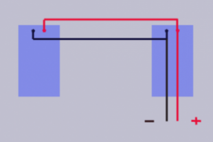
Picture 1.
In this version, we connect the terminal (+) of one module to the terminal (+) of the second module, we also connect the terminals (-) of both modules. From the terminal (+) and terminal (-) of any of the modules we output the ends (cores) for connecting the resulting group (battery) of two modules for connecting to, for example, a charge controller, if it is provided in our solar power station or to batteries, in case the battery charge controller is not provided.
If there is a need to connect three modules into a single battery, we do the same. We connect all three terminals (+), then - all three terminals (-) and also output the ends from the terminals (+) and from the terminals (-). No matter how many batteries you have to connect, everything repeats exactly the same.
Option two. Serial connection (Fig. 2):
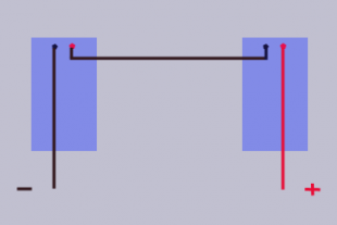
Figure 2
In this case, connect the terminal (+) of the first module to the terminal (-) of the second module. From the terminal (-) of the first module and from the terminal (+) of the second module, we derive the ends for connection to a charge controller or batteries. It doesn’t matter how many modules you connect, the principle is the same. The terminal (+) of the first to the terminal (-) of the second, the terminal (+) of the second to terminal (-) of the third, terminal (+) of the third to terminal (-) of the fourth, etc., exactly as many modules you need to connect.
Well, the third option. Series-parallel (Fig. 3):
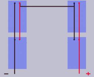
Figure 3
Indeed, sometimes you have to resort to this connection option. For ease of understanding, you first collect two groups of modules in parallel, in the figure the upper left and lower left are the first group. The upper right and lower right are the second group. After that, connect these two groups in series as if they were not groups, but two modules. A group can have not two modules, but three and four, and such groups can also have three and four or more.
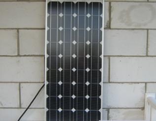
In practice, this is as follows. This is how the solar module looks from the front side, i.e. from the side of its working surface:
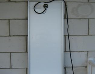
This is its back with the terminal box located on it.Just in it, and should be connected to the cable core terminals:
This is its back with the terminal box located on it. Just in it, and should be connected to the cable core terminals:
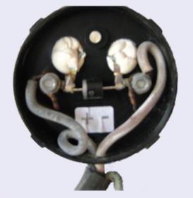
This is the terminal box itself with the cable cores connected. Pay attention to the cable cores being either crimped with a ring tip, or, as in my case, tinned with solder:
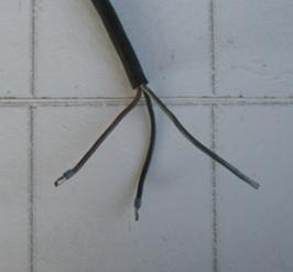
And these are crimped cable cores intended for connection in terminal clamps already under the roof of the house:
The third lived in my reserve. While it is not involved, therefore, it is not oppressed.
What is the need to connect modules in different schemes
Take a look. We know that we need 160 W of solar power, and devices, a charge controller, an inverter - 12 V input voltage. We purchase two 12-volt solar modules, each with 80 watts and connect them how? Right. Parallel. Thus, we provide a voltage of 12 V and the total power of the modules will be 160 W.
That is, we used the first parallel connection scheme. If we needed a power of 240 W and a voltage of 12 V, we would again have resorted to the first circuit, only there would already be three modules.
There are cases when there is a need to assemble a circuit not for 12 V, but for 24 V, 36 V and higher. What is it for? The fact is that the more modules we install, the greater the total power of solar modules. This in turn leads to an increase in currents in the circuits. We remember Ohm's law.
Power divided by voltage equals current strength. We increase power, the voltage remains the same, so the current increases. An increase in current forces us to increase the cross section of the wire. So imagine, the number of modules is increasing, so the area covered by them is increasing, hence the length of the wires is increasing.
Do not forget about the recommendation that I gave about switching solar modules under the roof of the house, in the article “Installation, connection of solar panels and their installation on the roof”. And we also need to increase the cross-section of these wires. That is, the inevitable rise in price of wires follows. To avoid unnecessary costs and rebuild the system to a higher voltage.
This can be achieved by connecting the modules in series. Suppose Figure 2 shows two 12-volt modules. Thanks to the serial connection scheme, we have achieved that they can be included in the 24-volt circuit. As for the mixed compound, it is necessary when both problems have to be solved simultaneously.
Conclusion
When using different variants of circuits, it should be borne in mind some important things that affect the resulting electrical characteristics obtained by switching modules into solar panels.
It is important!
So, for example, in a previous article, we said that when connected in series, the voltage of the connected modules is added up. If you connect two 12-volt modules, then the resulting voltage will be 24 volts. I do not now take into account such concepts as open circuit voltage, short circuit current, etc., so as not to fool you with a theory.
But we did not talk about what will happen to the currents, and this is important for you when choosing, for example, a solar charge controller. What input current controller do you want to choose.
So, you need to know: in a serial circuit, the resulting current will be equal to the current of the module with its lowest value, that is, the lowest current of all modules connected in series. That is why it is recommended to connect modules with the same characteristics in series so that, due to one “weak” module, not to lose the power that the modules could provide if they were all the same.
With a parallel connection, we said that the resulting voltage will be equal to the voltage of one module, regardless of how many you connect them in parallel.But the resulting current will be the sum of the currents of all modules connected in parallel.
In order not to cause difficulties for you, a mixed (or series-parallel connection), boldly, figuratively, of course, divide the entire group into smaller ones and finding out the current and voltage separately for each small group, consider these small groups as a separate module.
As you can see, there is nothing superintelligent in the scheme for connecting solar panels. Everything is simple. By the way, the same connection principle applies to batteries, but this is a separate song. It has its own nuances.
If this article helped you, click on one of the social media buttons so that the article can help others.
Boris Tsupilo
See also at bgv.electricianexp.com
:
