Categories: Featured Articles » Electrician at home
Number of views: 101940
Comments on the article: 2
Typical wiring diagrams in an apartment
 Living quarters for people are constantly being improved. They are increasingly appearing electrical appliances that improve life. Electricity consumption increases, and the wires laid during construction generate a resource: metal and insulation age, losing their properties from overloads, heating, ultraviolet radiation and mechanical stress.
The aluminum wiring operated since the times of the USSR has long been in need of replacement. Increased safety requirements canceled the TN-C system, which did not provide for the grounding of electrical appliance housings, the use of a potential equalization system, and protection against leakage currents.
Owners of old apartments do not always imagine how wires are placed in their rooms, because there are many options for laying them.
Types of circuits
The main classification of wiring is carried out by type of installation:
-
open
-
closed.
The first method allows you to visually observe the passage of tracks. It is more affordable, most often used in wooden houses.
It is more difficult to detect wires hidden in walls, floors or ceilings: they are not visible. They were laid differently in each building, but principles that take into account the construction period, wall materials, and installation technologies can be distinguished.
Aluminum wiring one-room apartment
Such a scheme is common, has been used for a long time, is well suited for more rooms, easy to understand and implement.
In old houses on each floor there is an electric panel with a meter, a batch switch to relieve voltage when working with metering devices and circuit breakers. All equipment is partitioned for each apartment separately.
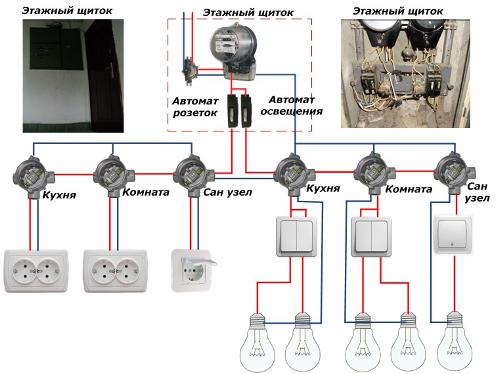
Fig. 1. A variant of the old wiring of a one-room apartment
The picture for clarity shows two junction boxes in each room, but most likely, the circuit of outlets and lighting are switched through one.
No ground loop is provided here. The circuit uses exclusively zero and phase, and the neutral wire should never be torn apart by switching devices. It is fed directly to all consumers through junction boxes, and is taken from the meter.
Most likely, simple twists with or without welding were used to connect the wires, although screw terminals can be found. The wires are most suitable for the zero assembly site.
The phase from the meter goes to the circuit breakers. In our example, one feeds all the outlets, and the other the room lights. If the apartment is equipped with an electric stove, then the voltage is supplied to it through a separate machine, and the wires used are reinforced power: up to 10 mm2.
Variations of the scheme are possible:
-
instead of machines used circuit breakers;
-
electricians when installing the wires after the counter mixed up the phase direction with zero (the circuit does not lose operability, but is more dangerous);
-
a group of vending machines was added and consumers were powered by a different scheme, for example, for a corridor.
Each specific circuit should be carefully understood, it is quite possible that there are jumpers, additional wires, even installation without junction boxes.
Understanding the principle of circuit design helps a simple way:
-
turn on all lighting devices and use electrical appliances in sockets;
-
alternately turn off consumers with automatic devices in the distribution panel and observe the extinct lamps and disconnected devices in outlets;
-
analyze changes, record or remember information, draw conclusions.
Read also: What is the danger of old wiring
Types of hidden wiring
In practice, the main lines are laid:
-
on the ceiling or inside it;
-
under the floor;
-
in combination.
The layout of the wires inside the ceiling
It used to be widely used in buildings made of bricks and concrete panels, as the main version of the wiring. In modern construction, it is also often used.
All routes with wires from the switchboard are routed vertically over the wall or inside it through the gates or mounted pipelines. The interiors of ceiling slabs are usually made with ducts for wiring, but gouging or wall mounting is allowed for suspended and suspended ceilings.
In the same way, an approach is made to the lamps, all the switches and electrical outlets located on the walls.
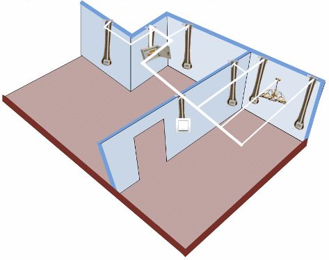
Fig. 2. A variant of the wiring diagram inside the ceiling
With a competent approach to installation, all wiring is oriented in perpendicular planes: this eliminates damage to insulation and metal during future drilling of walls to fix various objects on them. Horizontal lines from the ceiling must not be lowered below 15 cm for the same reasons.
Junction boxes are attached to their machines to supply voltage to the nearest point. Installation in them is carried out according to the circuit diagrams.
Layout of wires under the floor
This option began to be used in new buildings with a rigid concrete base and the creation of durable pipe lines under the floor covering with subsequent pouring with mortars. Such measures reliably protect the insulation and metal from mechanical damage.
Cables and wires in the walls for outlets and fixtures are protected by pipes or mounting boxes.
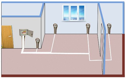
Fig. 3. A variant of the layout of the wiring under the floor
Combined Wiring Methods
Here both methods are combined, but similar schemes have many distinct nuances.
Factory panel houses
They have the insides of wall and ceiling plates made by channels for laying electrical circuits. Highways connect all consumers through junction boxes with an input shield. The wires are drawn into these lines.
Please note that here the pipes may not be located at right angles, but at sharp angles. Their location can only be determined electronic devices with hidden wiring search functions.
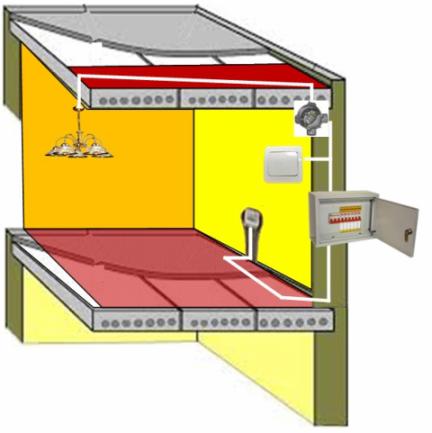
Fig. 4. A variant of the old wiring in the apartment
Houses built during the Khrushchev era
The panel old buildings used a fairly simple wiring arrangement, significantly reducing construction technology, but far from safe.
"Aluminum noodles" to the sockets is led under the boards of the wooden flooring, and to the lamps it goes down from under the floor of the upper neighbor through an opening in the ceiling plate. This is the most dangerous installation, which usually has no protection. Twists without welding are often found here, and the insulation begins to break down.
Such wiring must be completely redone, but this is a complex and expensive undertaking.
Each of the considered schemes can have different deviations from the project, even in neighboring apartments of the same house. A specialist can identify them by conducting electrical measurements. This work is often carried out under stress, which is dangerous.
Therefore, without a solid knowledge of safety rules and practical skills in working with electrical appliances, it is better not to take on the independent re-equipment of your apartment.
Read also on this topic: Wiring diagrams in the apartment and house
See also at bgv.electricianexp.com
:
