Categories: Electrician at home, Automata and RCD
Number of views: 138492
Comments on the article: 7
Schemes for connecting RCDs and differential machines
 Among the protective devices in home wiring, protective shutdown devices (RCD) and differential automata (difavtomaty). Manufacturers produce them with various types of designs for use in single-phase and three-phase power supply schemes. All these devices have a common algorithm of work.
Work principles
By and large difference of RCD from differential automaton consists in the absence in the circuit circuit breakerresponsive to excess current loads. Therefore, the connection diagram of a single-phase or three-phase RCD from the connection diagram of a differential automaton differs only in the absence of this function. To protect against short circuits and unacceptable loads, additional current protection is required in it.
A common element of these protections is a circuit based on a comparison of the current vectors entering and leaving the device, which, when deviating from the set limit values, turns off the electrical equipment.
The elemental base on which this circuit operates may be different, for example, based on electromagnetic relays or semiconductor elements. To understand how to properly connect an RCD and a differential circuit breaker to an electrical network, we consider the first design option for a simplified single-phase network. Internal elements of static devices work according to the same algorithm. Therefore, their connection is completely similar.
Normal power mode
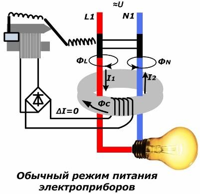
When turned on RCD under load, through its current conductors mounted inside the toroidal magnetic circuit, the load current flows. If the insulation quality in the circuit is good, then there will be no leakage currents through it. The current I1 entering through the phase current lead L1 will correspond to the value of the current I2 emerging from the magnetic circuit and is simultaneously directed in the opposite direction.
In this case, the magnetic fluxes ФL and ФN, formed from phase currents and zero, will also be equal in magnitude and opposite in direction. During the passage through the magnetic circuit, magnetic fluxes add up in it, mutually destroying each other. The total magnetic flux of the magnetic circuit Фс is equal to zero.
The described option considers the operation of an ideal device that exists only in theory. In practice, some kind of imbalance in the ratios of F1 and F2 always appears, but it is very small and does not affect the operation of the circuit.
Leakage Current Mode
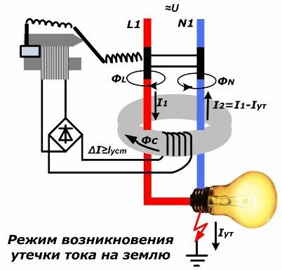
In the event of insulation failure, part of the phase potential will begin to drain to the ground, forming a leakage current Iout. The current value in the neutral conductor I2 will decrease by the same amount. It will form a smaller magnetic flux ФN. When adding magnetic fluxes inside the magnetic circuit, an excess of flux F1 over Ф2 will occur. The total flux Fs will immediately increase and will induce an EMF coil wound around it.
Under its action, a current ΔI will appear in the closed loop of the coil, proportional to the leakage current. If the user exceeds the value set by the user, the electromagnet will trigger, disengaging the latch of the release integrated in the device, which will trip and release the voltage from the entire protected area.
Power Off Mode
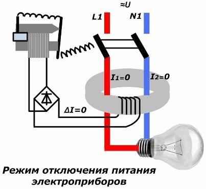
As you can see, all the shutdown protection works automatically. But in order to re-enable the RCD in the work, you must perform the following actions:
1. analyze the state of the electrical circuit to determine the cause of the shutdown;
2. eliminate the identified malfunction;
3. Only after that use the manual switch lever on the RCD or difavtomat machine.
The occurrence of re-triggering of an RCD must be considered as a consequence of poor insulation of electrical equipment and immediate measures should be taken to restore it. The coarsening of the protection settings, as well as its blocking, is unacceptable.
During the initial installation of an RCD or a differential machine in the wiring diagram, it is sufficient to correctly connect the input and output wires of the phase and zero to their terminals. They are clearly marked on all buildings.
Scheme of connecting a single-phase RCD to a two-wire network
To indicate the input terminals of phase and zero, the inscriptions "1" and "N" are made, and the output - "2" and "N". For devices using an electronic base, it is important to properly connect the neutral because you can not be mistaken with its polarity. Otherwise, the probability of damage to the component parts of the electronic circuit is high.
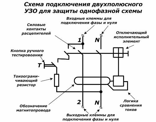
The design of the device uses the possibility of periodic testing during operation to determine serviceability. To this end, the “T” button is installed, when it is turned on through a current-limiting resistor and a closed contact, a chain is created for the flow of a part of the current, affecting the occurrence of an imbalance of magnetic flux, which provides protection shutdown. If the test button T is pressed on the RCD while energized, and the shutdown did not occur, then this clearly indicates that the device is malfunctioning.
When the RCD is manually turned on, 3 contacts are closed immediately in this circuit:
1. phase conductor;
2. zero current lead;
3. Circuit testing electronic circuit.
During the occurrence of leakage currents when the protection is triggered, these same three contacts automatically break their chains.
Connection diagram of a three-phase RCD to a four-wire network with a common neutral
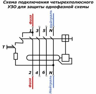
The basis for the installation of three-phase RCDs and diflavtomats is the previous scheme. In it, too, it is necessary to observe the polarity of each phase and zero. To do this, connect the input circuits to the odd terminals, and the output circuits to the even ones.
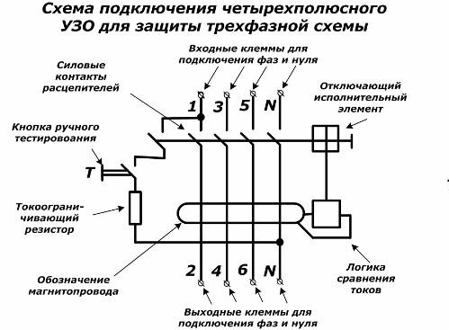
Such an RCD works when there is an imbalance of magnetic flux created by currents from all four current conductors.
Scheme of connecting a three-phase RCD to three single-phase networks with a common neutral
This development allows one device to immediately protect three single-phase electrical circuits.
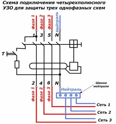
To do this, just select the installation location that allows you to use the bus to connect to the output of the neutral protection for its separation on networks No. 1, 2, 3.
Scheme of connecting a three-phase RCD to a three-wire network without neutral
In the particular case of protection of electric motors operating from three phases without neutral, the zero terminals on the RCD are not involved.
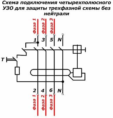
However, with such a connection, it is better to use electromagnetic designs with mechanical trip units. Static models require voltage supply to the power supply for operation. It can be connected between phase and neutral wires.
In addition, the absence of zero potential excludes the function of periodically testing the health of the device under voltage, which is not very convenient. Therefore, such a connection requires modifications to the internal structure.
Scheme of connecting a three-phase RCD to a single-phase network
This is not a very rational method, but it is resorted to during sequential installation of a single-phase network at the beginning, followed by the addition of two more electrical circuits for general protection, which will be created after a certain time.
In this case, it is important that the phase is connected strictly to the current lead through which the RCD is tested in working condition. For this, when the power contacts are turned on and the test button is pressed, “ringing” the resistance between the input of each phase and zero.
This must be done on a dismantled RCD without voltage. On two terminals, the resistance will correspond to infinity due to broken contacts, and on one it will show the resistance value of the current-limiting resistor. This terminal should be connected.
Differences between RCD connection schemes from differential machines
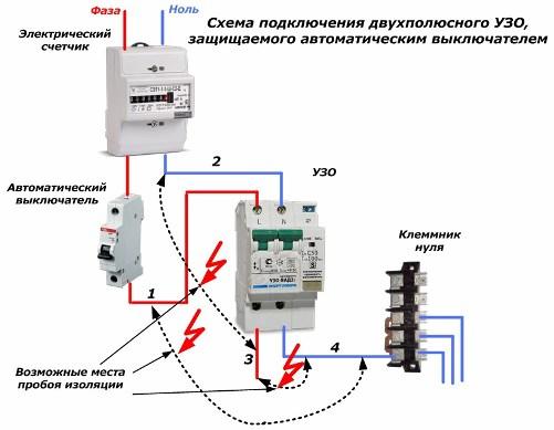
At the very beginning of the article, it was noted that the RCD has no built-in protection against overload and short circuit currents that can occur at any time and burn the device. It must be protected. Therefore, before each RCD, it is necessary to mount a circuit breaker with a setting that ensures the operability and safety of the RCD.
In addition, the circuit breaker saves the RCD from overload currents, it also protects against three types of short circuitthat may occur in the circuit with insulation failures between:
1. the output phase wire of the device 3 with the input neutral wire 2;
2. output neutral wire 4 with input phase wire 1;
3. between output wires 3 and 4.
If in the first two cases the short circuit current passes through only one current path located inside the RCD, then in the third case both lines are loaded. This type of circuit is the most dangerous.
Differential automata they do not need such protection, they have it built-in. Therefore, the cost of these devices is higher. The connection diagram of the differential machine does not require additional installation of a circuit breaker.
Reliable and long-term operation of the RCD and the differential machine is ensured by the correct connection, taking into account the specific conditions of the operating circuit, the precise setting of the settings for operation, providing protective functions.
See also at bgv.electricianexp.com
:

