Categories: Electrician at home, Sources of light
Number of views: 35801
Comments on the article: 3
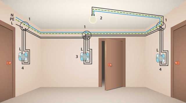
Lighting control from two, three or more places
One of the most common tasks for an “apartment” electrician is to install one or more fixtures. Usually this does not create any problem, because connecting one switch is quite simple. But often you need to make sure that the bulb turns on from several places, for example, from two, more - less often. In this article, we will consider lighting control schemes with the help of several switches.
Light control from two places
This problem is often found in private houses on a precinct, for example, near the front door and gate, at the entrance to the courtyard, as well as in houses with several floors, so that it is possible to turn on the light from any floor and safely go down the stairs.
The main problem is that if you install two ordinary switches on one lamp, then no matter how you connect them, they either must be on or both are off. Therefore, it will not be possible to fully control lighting from several places according to such a scheme.
In order to solve this problem use circuit breaker. Such a device is more correctly called a switch. Let's look at the circuit and features of the passage switch.
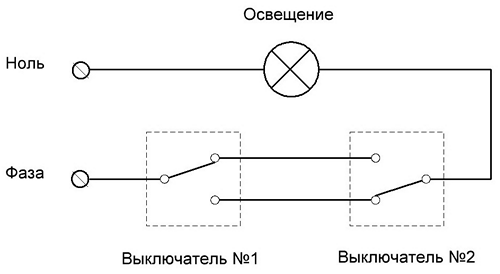
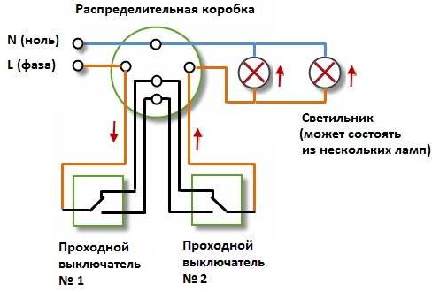
Here we see that the circuit breaker is different from the usual circuit breaker. If in the standard version the contact is either closed or not, then the moving contact closes either on one line or on another, that's why I called it a switch.
If you still do not understand how this circuit works, consider its states:
1. On both switches, the key is pressed to the “UP” position - the light is on, current flows through the “upper” wire (if you look at the above diagram).
2. The first switch is in the “DOWN” position, and the second is “UP” (or vice versa) - no current flows through the circuit, the lamp does not light.
3. Both switches in the "lower" position - current flows through the "lower" wire, and the lamp is on.
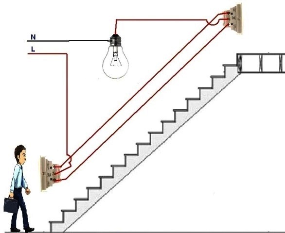
The circuit is simple enough to build:
1. Directly connect zero to the lamp from the distribution box or in another way, depending on the circumstances
2. A three-core cable extends to the switch closest to the power source (say 220V network). The first core is connected to the phase and the middle moving contact of the switch. Below we present the terminals of the switch and its circuit repeatedly.
3. The two remaining wires are connected to a pair of output fixed contacts and a second switch.
4. From the middle movable contact of the second switch, we take the outgoing phase and connect to the lamp.
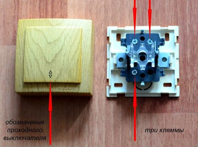
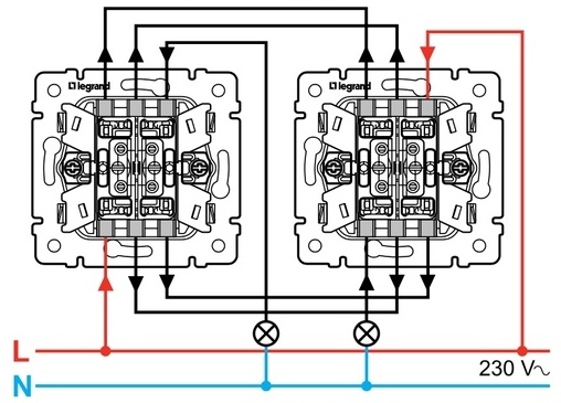
The passage switch differs from the usual one in that it has a switching contact, so there are three terminals for connection instead of two on it. They are also one, two and three-keys. Then this scheme is simply duplicated in accordance with the number of keys and lamp groups as it is shown in the figure below.
Interesting: If you have the opportunity to connect a phase with zero to each of the switches with minimal cable costs from different junction boxes, you can use an alternative version of this circuit. It differs in that the bulb is connected to a movable contact, and the phase with zero is fixed and, as it were, is mirrored.

How to mount
For ease of installation, you need to imagine in advance how you will lay the cables, which is closer to the first switch and what is closer to the second - a distribution box with an incoming phase or a lamp, or maybe both ... But in most cases you need a simple three-wire cable or cable, Depending on the operating and installation conditions, the following are suitable:
-
VVG 3x1.5;
-
PVA 3x0.75 ... 3x1.5;
-
ШВВП 3х0.75 ... 3х1.5;
-
Or a foreign analog of NYM of similar sections.
You can use the wires from these wires separately, as well as buy a single-core wire of the PV brand, corresponding to the flexibility class, for example, PV-1 is a rigid monolithic version. In this case, the probability of error will be reduced, especially if you choose multi-colored veins. The picture below shows one of the mounting options in a more visual form:
Management of three or more places
If you want the lamp to turn on from three places or more, cross switches go into battle, they are sometimes called intermediate switches. The circuit is shown below.
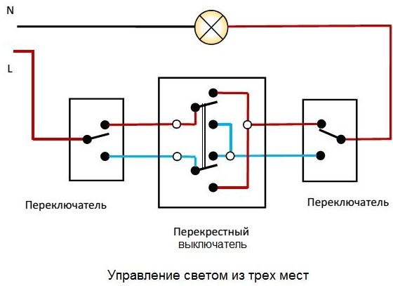
Beginners can be frightened by the light control circuit from three places, but let's understand it. Cross-over switch - this is the same pass-through switch with only one key at the same time two groups of contacts are switched. The only difference in the visible part will be that on the cross 4 terminals for connecting wires, and on the passage 3.
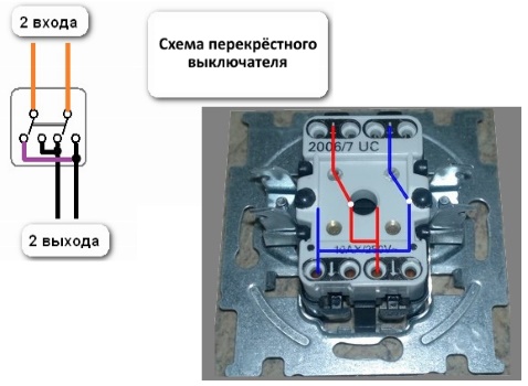
Why do I need a cross switch? Then, in the lighting control circuit from two places, the passage switches are connected by two wires, and due to this, the necessary power supply line of the lamp is selectively connected. Here you need to also switch this pair of wires between each other, for this they use a cross switch.
The logic of the circuit is simple, let's understand only for brevity we designate the switches as A, B and C, from left to right according to the circuit.
1. All three switches are in the “upper” position — current flows along the red line and the lamp is on.
2. Switch “A” in the “down” position, the rest “up”. Then the phase is applied to the blue line, and the lamp is connected to the red one - the current does not flow. If you switch the switch "B" - "down", the lamp will light up, because the current will go along the red line in the diagram, the same will happen if you switch “C”, only the current will go along the blue line in the diagram.
The remaining provisions are similar.
Assembling a three-place switching circuit is quite simple. We connect the phase to the middle contact of one of the extreme walk-through switches, and from the second pass-through, from its middle contact, lay a wire on the lamp.
From the first pass-through in any sequence and to any terminals we connect to the cross, and, from its second pair of terminals, two wires to another pass-through. Such a connection is illustrated more clearly in the figure below.
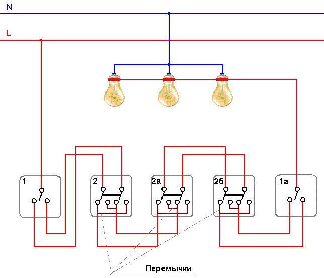
A further increase in the number of switches for controlling one luminaire is simply by the principle of adding cross-switches to the gap. Below is a light control circuit with 4 spots.
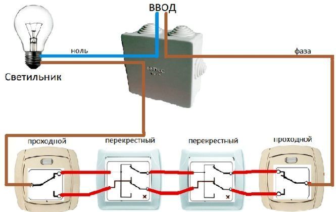
The same scheme, but for control from 5 places:
Conclusion
The above light control circuits from several places are quite simple, but they have one drawback - it is easy to get confused in the wires, as well as their high consumption. This may not be economically feasible given the strobes or the cost of laying the line in an external way, it may be easier to install several lights on your route. However, there is an easier way - pulse relays for lighting control, we examined them in detail in this article: Impulse relays and their use
See also at bgv.electricianexp.com
:

