Categories: Featured Articles » Electrician at home
Number of views: 68935
Comments on the article: 14
Wiring diagram in the apartment
In the practice of any home master, questions periodically arise related to the finalization of the electrical circuit, when it is necessary to install an additional outlet, hang a new lamp or completely remodel the room.
The question immediately arises: how is the wiring diagram of the electrical wires made, where should I connect to it?
The situation is aggravated when the building is old, the apartment was replaced by several owners, each of whom carried out repairs to his taste. As a result, inside the decorative coatings are hidden all points of electrical wiring, and the routes of laying its cables and wires are unknown.
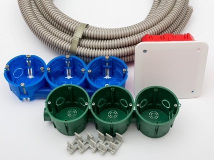
The principles of building an electrical circuit in an apartment
Any wiring is created by common methods and something, but it differs from all other laying schemes.
Mandatory Schema Elements
The basis for creating electrical wiring is electrical switchboardto which electricity is supplied from the supplying organization. It can be installed at the entrance to a private house, on the staircase of the entrance of a multistory building - floor or directly inside the apartment.
Electricity in the apartment panel from the input immediately goes to the electric meter - a device that takes into account its consumption. After it, it is distributed along the supply lines to consumers with cables and wires.
To protect the circuits, automatic devices are used that cut into the circuit inside the apartment panel in front of the cable going to the consumer.
Distinctive features
Each specific wiring diagram is necessarily different from similar developments due to the use of numerous designs of various models of electrical devices, wires and cables with their installation according to standard or individual projects using different methods.
Ways to supply voltage to consumers in the apartment
The electric current from each working household appliance is summed up in the apartment panel and is taken into account by the meter through which the total load passes. Therefore, the current paths of the apartment panel are made of thick section, excluding thermal overload of the wiring, aging of the insulation.
To consumers from the apartment shield, wires are laid in a smaller section: the load through them is lower. But the material and cross-section of the core are selected according to directories that take into account the operating conditions of the wires and the power transmitted through them.
There are three possible ways to implement the scheme:
-
by a loop (buses), when a common wiring trunk is created through junction boxes, and from them there are branches to electrical points (sockets, switches, lamps);
-
the radial method, which consists in supplying voltage to each outlet with a separate cable that goes directly without gaps and connections from the protection of the apartment shield;
-
in a combined way, combining the elements of the first two principles.
Supply voltage loop
All ends of electrical wires and cables are switched inside junction boxes. An exclusion map is created to connect them.
An example is the wiring diagram used in high-rise residential buildings of a forty-year-old construction. As a sample, we consider the structure of the old wiring of a one-room apartment.
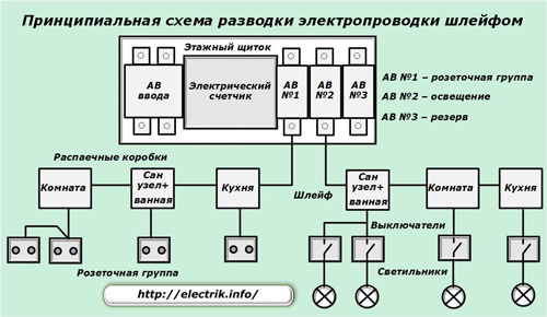
An electric meter and two circuit breakers were mounted inside the access panel. One was used for the outlet group, and the second worked for lighting. Cables or more often wires - “aluminum noodles” to three (sometimes four) junction boxes went from them in a loop:
1. rooms;
2. kitchens;
3. San node and bath.
Both loops were laid by parallel lines to each box, commutated in it.Since the load on the wiring was small before, separation by the thickness of the wire was not applied. The whole circuit was completely mounted with a section of aluminum conductors of 2.5 mm2.
A junction box for the sanitary unit and the bathroom was installed in the corridor and connected with wires to block from the socket and two-gang switchthat controls the lighting of both rooms.
The diagram shows a consumer protection option. circuit breakersconnected separately to sockets and lighting devices. The principle of consumer management at the place of their location in the rooms was also often used. For example, AB No. 1 protects the equipment of the kitchen and bathroom, and No. 2 protects the corridor and the room.
Inside one room, several outlets were often connected with a loop, and lighting was a three-arm chandelier controlled by a two-key switch.
The supply of voltage to consumers can be performed according to other principles, when part of the load is connected through the third backup circuit breaker of the apartment panel. To determine how to connect sockets and switches, proceed as follows:
-
light all the lamps and connect working electrical appliances, such as a desk lamp or a razor, to sockets;
-
they turn off any circuit breaker in the panel and consumers who have stopped working monitor it;
-
record for memory;
-
turn off the next machine and record the changes;
-
analyze information.
Radial voltage supply
A housing shield distributes electricity to circuit breakers, as in the previous case. In this situation, they are more carefully selected according to technical characteristics for each consumer according to the individual load current.
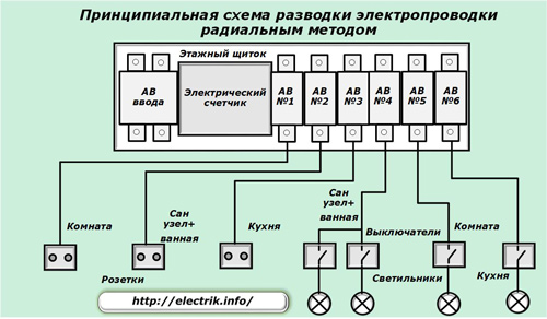
The cable connects sockets, switches and fixtures directly to the circuit breakers without using any additional connections.
With this principle, electrical wiring provides increased operational reliability by disconnecting only the consumer at the fault from protection. However, in this case it is required:
-
increased number of circuit breakers;
-
large dimensions of the housing shield for their placement;
-
long cable lines.
Due to this, the material costs of creating a scheme and its cost increase.
Combined voltage application
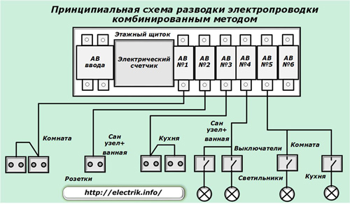
The method combines two developments: a loop and a radial connection, taking into account their application to local conditions. Due to the correct selection of loads creates a reasonable cost savings.
The principles of laying cable lines
Whatever electrical connection scheme is chosen, for its implementation it is necessary to connect the automatic devices of the apartment panel with consumers with wires.
There are the following methods of cabling on building structures:
-
on the ceiling;
-
on the walls;
-
under the floor;
-
mixed method.
Ceiling cabling
The traditional old scheme, which is often resorted to now.
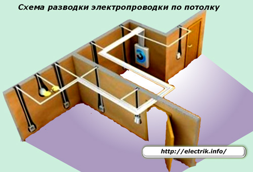
Cables from sockets, switches and a panel along vertical lines rise to the ceiling and go under it into the ceiling. When it becomes necessary to turn and connect the wires to the junction box, for example, to connect a switch, they create only a right angle of at least 15 cm from the top.
This method allows in the future to avoid accidental damage to hidden wiring when drilling walls for mounting shelves, paintings and other elements.
Laying cables on the wall
The method resembles the previous one, but the cable lines are sent only along the walls.
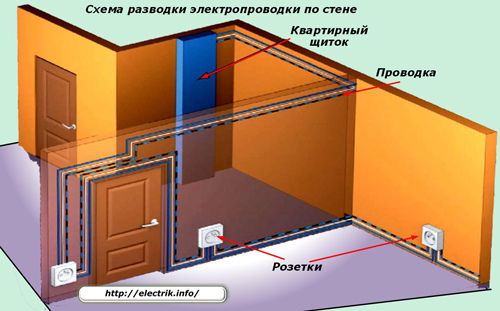
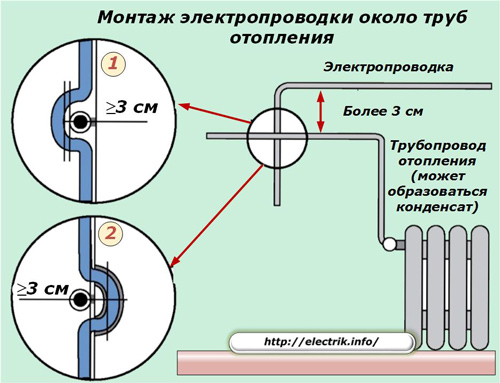
There may be obstacles in the way of the electric main: pipelines for water supply, sewage, heating, gas pipelines. They must be bypassed, creating an air gap as an insulating, dividing section of not less than 3 cm.
Floor cable routing
This method began to be used relatively recently in the construction of new buildings. Cables from the housing shield are lowered down, laid under the floor covering, protect from mechanical stress. To the outlets they are displayed vertically.
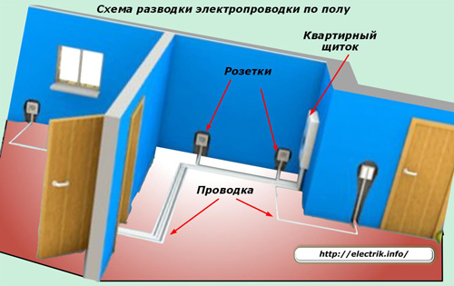
When connecting sockets with a loop, jumpers are laid on the floor in pipes or shredded walls.
To connect the luminaires and switches mount junction boxes.
Features of the wiring in prefabricated houses
When the factory method of manufacturing high-rise buildings is created, the same templates of wall and ceiling panels are created. Inside, empty channels for laying wires are immediately made.
For technological reasons, their direction may differ from the strict orientation vertically and horizontally.
The first panel buildings, called the Khrushchev, have a specific electrical wiring, laid under the wooden floor of the apartment. To the sockets it rises vertically in the cavity of the walls, and to the lamps and switches it is led through the hole in the concrete slab of the neighbor’s floor from above.
In this way, before trying to save material costs for wiring, but neglected the safety features.
How to make a DIY wiring diagram in an apartment
Electrical equipment requires compliance with strict operating rules. Incorrect connection to the voltage network creates increased risks of personal injury. For this reason, all work with electricity is carried out by trained specialists who have passed training and passed exams.
Independent connection of electrical appliances is usually not a lot of difficulties, it ends safely even with a few minor errors. However, when engaging in such activities, it is necessary to first study the safety rules and current regulations.
The wiring diagrams are handled by design organizations that have received state permission for this type of activity. It is completely permissible to try to make her project with your own hands and get advice from a specialist on it.
This will require:
-
create a room plan on a scale or use the technical drawings of the developer;
-
mark on it all the furniture and large items in compliance with the proportions;
-
determine the installation locations of electrical consumers, evaluate their load;
-
plan the placement of electrical points: sockets, switches, lights, junction boxes;
-
to mark the routes of electrical wiring on the walls, ceiling or floor;
-
make a sketch for each room.
Floor plan
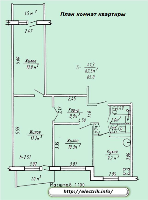
A similar drawing should be stored in the documentation of the housing and communal services. If there is no access to it, then you can use tape measure and draw a simple sketch yourself on paper.
Furniture Arrangement
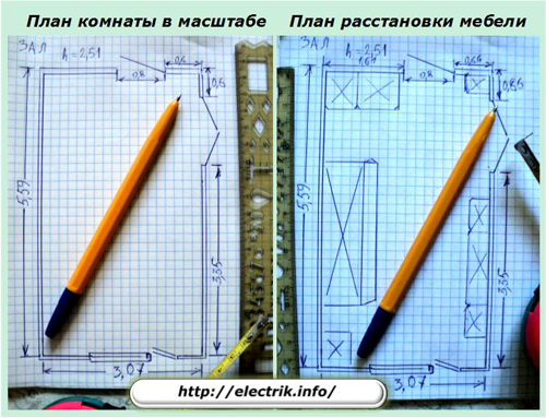
The stationary placement of bulky items in the room should not clutter up sockets and lamps. Access to the switches must be made free, and their use convenient.
Therefore, all electrical points are placed taking into account the free area of building structures. It eliminates use of additional portable extension cords.
Assessment of power consumption of electrical appliances
Analysis of the created loads allows you to:
-
group consumers;
-
pick up protection for them, switching devices;
-
choose the design of cables, wires.
Selection and calculation of electrical wiring is carried out according to the applied load for an open and closed method of operation using electrical reference books.
Determining the installation locations of electrical points
Planning the location of switches, sockets and fixtures is carried out taking into account the solutions to the issues discussed above.
The coordinates of each electrical point are indicated on the sketch. They apply markings on building structures. It will allow you to design the direction and calculate the length of the wires and cables for their purchase.
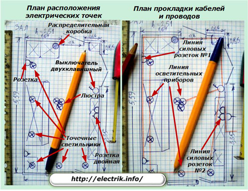
Such a plan is made up for each room. It will become the basis for creating an electrical wiring diagram in the apartment, help to acquire the necessary material resources, and perform optimal installation work.
Having saved it in the home technical documentation, you can always restore the features of the electrical circuit in memory for carrying out its modifications and modernization.
See also at bgv.electricianexp.com
:
