Categories: Electrician at home, Electric installation work
Number of views: 18897
Comments on the article: 1
How to make grounding in apartments and private houses
Electrical installations are closely related to safety issues. With a sharp increase in modern loads, they began to receive increased attention.
For this, various protective devices and ground connection schemes are used. Thanks to the connection to the living room of the PE-conductor, it is possible:
-
reduce the devastating consequences of emergencies;
-
prevent fires from faulty electrical equipment;
-
save people from electric injuries and death.
Protective grounding helps solve all these issues.
Principles for the implementation of human protection against emergency currents to earth
How does grounding work
High voltage electrical energy is transmitted over long distances using transformers.
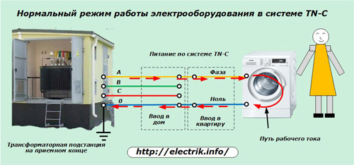
Any household electrical appliance performs an action when current flows through it. The path for it is formed by a closed ring from the generator to the consumer through the wires of the “phase” and “zero”. The potential difference between them determines the magnitude of the applied voltage.
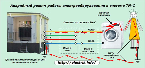
When a breakdown of the insulation of the phase wire to the body and ground occurs, the applied potential mostly flows along the path of least electrical resistance through randomly formed chains: metal pipelines, water networks, reinforced concrete fittings, elevator equipment ...
A person caught in the path of this current receives an electrical injury that can end tragically. To partially reduce the consequences of such an accident, an RCD or a difavtomat, connected to a two-wire circuit, helps. They turn off the emergency current through the human body with a short delay, limiting its thermal effect on the body.
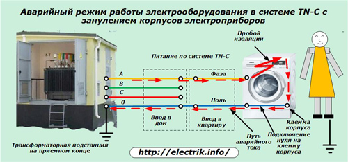
To prevent such an accident, it is used Grounding. This is a method based on connecting the housing of the household appliance to the neutral conductor of the circuit without using a protective ground loop.
When an insulation breakdown occurs on the case, the potential of the phase of the circuit automatically turns out to be shorted to zero. Short circuit current occurs immediately. It should be felt by the protection of the input machine and relieve voltage from a working faulty device. With this method, the main attention is paid to the accuracy of the protective devices according to the settings assigned to them.
Using the method of zeroing, you must be careful, you can not confuse the places of zero and phase. Otherwise, the potential of the electrical installation will be constantly applied to the enclosure: instead of a protective connection, a direct prerequisite will be created for electrical injuries.
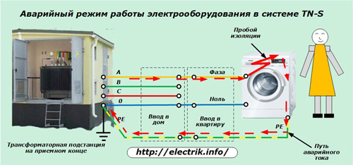
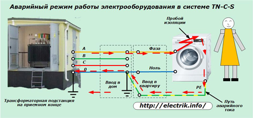
In buildings equipped with electrical wiring by TN-S system, during breakdown of phase insulation, emergency current is diverted through the protective PE conductor.
At the same time, RCD devices and difiltomata reacting to the appearance of a leakage current through a protective zero, remove the voltage from the controlled area with damaged insulation. Man is spared the effects of emergency current.
According to the same algorithm, protection works in buildings converted to a TN-C-S system, in which grounding additionally uses the splitting of the PEN conductor into a working and protective zero at the entrance to the house.
In this way, the protective grounding of the building saves a person from electric shock during breakdowns of insulation on the housing of all household appliances. However, this is not his only protective function.
In the cottage and in a separate private house, grounding allows you to implement in the complex:
-
equalization of potentials generated during the operation of electricity;
-
lightning discharge discharge directed to the building in the lightning protection system;
-
elimination of high-frequency interference arising from operating television and radio equipment.
Grounding Specifications
Design reliability
The energy of lightning can reach very large values. Its short-term discharge to the earth of hundreds of kiloamps burns through the roof of the house, destroys tree trunks. The grounding design must withstand this effect and reliably divert such a large current from the building.
For this, thick metal corners of at least 40x40 mm are used during installation, strips with a cross section of 50 mm square. and pins that securely connect by welding. Elements of smaller transverse areas used in the ground loop may simply not withstand lightning energy.
Circuit electrical conductivity
The terrain on which the building is located has various electrical characteristics. Rock, sand, clay, loam, marshy soil conduct electric current in different ways.
Depending on the time of the year, the filling of aquifers with groundwater changes. All this requires research by a special laboratory, since it affects the choice of grounding design, its deepening, and, consequently, the cost. Earthing switches must reliably pass current through the topsoil into the depth with stable electrical characteristics. And its conductivity properties periodically deteriorate due to freezing or drought.
The metal of the ground loop works in a humid soil environment and is susceptible to corrosion. Its scales move away soil particles from the ground electrode system over time, worsening its electrical contact.
Painting of grounding elements is unacceptable due to a violation of its dielectric properties. To protect against destruction by chemical reactions occurring in the soil, steel parts are coated with a layer of zinc or copper.
Protected electroplating methods earthing switches can work for several decades. But, they also need periodic monitoring of the technical condition, which is performed by measuring the resistance between their metal and soil.
Electrical laboratories that assess the quality of the ground loop use powerful sources and meters of high accuracy current or voltage drop. One of the principles of such measurements is shown in the picture.
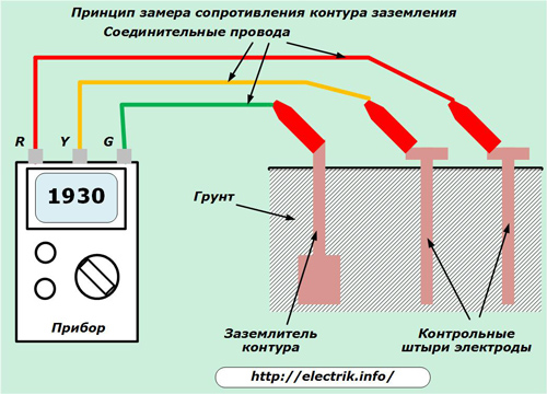
Near the ground electrodes, two control pins acting as additional electrodes are driven into a depth of 5 ÷ 10 meters at a certain distance. Then the open circuit voltage of the device is calibrated, fixed and fed first to the control pins, and then to the ground electrode of the circuit and alternately to each of the electrodes.
With all connections, the voltage drop in the circuit is monitored. Based on the data obtained, calculations are made. The worst result with the highest resistance is taken as the basis of measurement.
When an analog instrument is used, the operator performs the calculations and measurements manually. Models equipped with microprocessor devices allow automating the process and speeding up the analysis.
The described measurement algorithm by the electrical laboratory is described in order to show that ordinary testers, multimeters and megaohmmeters to assess the quality of grounding are not suitable. Their result will not be accurate.
Grounding device designs
To make ground loop You can do it yourself or buy a ready-made kit. But, before that, it is necessary to find out the electrical characteristics of the soil and get advice from the specialists of the local laboratory performing such measurements. They will tell you the most acceptable solution.
The best time to plan the ground loop coincides with the design phase of the house. At this stage, it is convenient to calculate and combine it with the design of the lightning rod and other safety systems, fit it nicely into the design, and assign the construction to the builders.
However, most often grounding, like all electrics, is remembered after the construction of the building. In this case, several typical designs are considered.
Simplified design for short-term grounding
The easiest way to make an earthing switch is as follows:
-
hammer a two-meter corner, a pin or a rod of reinforcement into the ground (you can bury a steel sheet);
-
connect to the created electrode a copper wire with a cross section of at least 4 ÷ 6 mm square;
-
The second end of this conductor should be removed and mounted on a metal strip used as a bus, and all housings of household appliances should be connected to it.
However, this method is unreliable: it works for a limited time. Most often it is used on mobile cabins, wagons that are operated in one place for several months, and then move to another facility.
Horizontal circuit of three ground electrodes
This design works in the topsoil. For earthing, pipes or corners are used, which are sharpened at the lower ends for better penetration into the ground when driving.
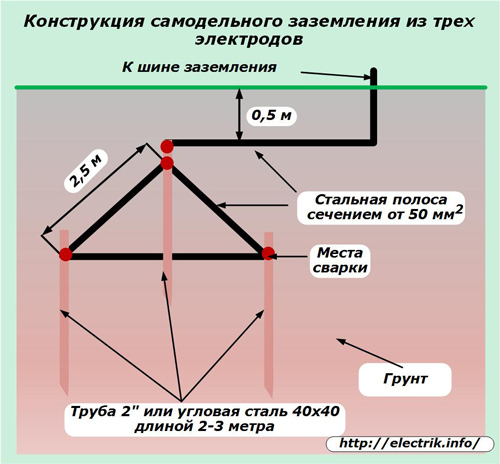
A trench in the form of a triangle or a segment is dug on the surface of the future contour, if a tape contour is used, when only it can be used according to the terrain. At the corners of the dug equilateral triangle, electrodes are driven in to the entire depth, leaving room for their connection by welding to a steel strip.
After the final installation of all metal elements, strip steel is brought to the surface for connection to the building's bus, and the trench is filled up.
The correctness of the calculations and installation will show the measurement of the electrical characteristics of the circuit. If a marriage is detected, you will have to hammer and connect an additional ground electrode, repeat the measurement. In the same way, the degraded circuit characteristics that arise after several years of operation are corrected.
A horizontal circuit of sixteen grounding conductors
This design has greater power to transmit emergency currents to the ground and is used where soil soils have high electrical resistance. It requires a plot of land measuring 25x25 meters and a significantly larger amount of material.
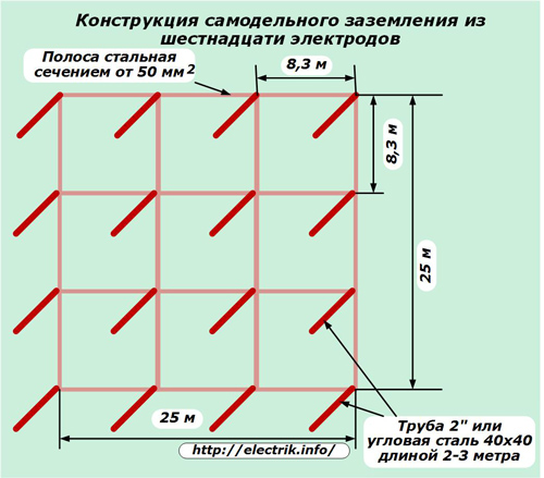
Manufacturing and verification technology is consistent with the previous method.
Vertical outline
Manufacturers of industrial grounding conductors produce various sets, which during installation take little time and at the same time are adapted for long-term operation.
One such design consists of four vertically clogged copper-plated pins. They are mounted from two-meter elements using a durable threaded adapter. Screwing them into each other allows you to consistently deepen the electrode to a depth of 12 or more meters.
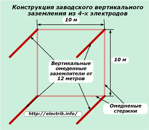
A special electric vibratory hammer drives each shaft in a short time. To reliably connect the electrodes to each other with copper-plated rods, special clamps are used. In the same way, the circuit is connected to the building bus.
However, even for this design it is necessary to carry out electrical measurements.
Thus, in order for the grounding to reliably protect the residents, and, at the same time, the electrical equipment of the apartment or private house, it is necessary:
-
specify the functions that it should perform;
-
analyze the electrical characteristics of the soil;
-
choose the most suitable design;
-
to mount correctly;
-
take measurements of electrical characteristics and do not forget to take them every next year.
Only in this case, a real check of your work by a lightning discharge will not do you any harm.
See also at bgv.electricianexp.com
:

