Categories: Featured Articles » Home automation
Number of views: 116550
Comments on the article: 2
Temperature sensors. Part three. Thermocouples. Seebeck effect
Thermocouple. A brief history of creation, device, principle of operation
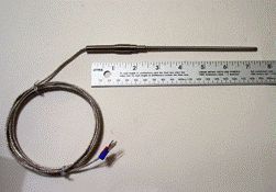 Externally, the thermocouple is arranged very simply: two thin wires are simply welded together in the form of a neat little ball. Some modern digital multimeters Chinese-made equipped with a thermocouple, which allows you to measure the temperature of not less than 1000 ° C, which makes it possible to check the heating temperature soldering iron or iron, which is going to smooth the laser printout to fiberglass, as well as in many other cases.
The design of such a thermocouple is very simple: both wiring are hidden in a fiberglass tube, and even do not have insulation noticeable to the eye. On the one hand, the wires are neatly welded, and on the other they have a plug for connecting to the device. Even with such a primitive design, the results of temperature measurements are not in doubt, unless, of course, accuracy of measurement of class 0.5 ° C and higher is required.
Unlike the Chinese thermocouples just mentioned, thermocouples for use in industrial plants have a more complex structure: the measuring section of the thermocouple itself is placed in a metal case. Inside the case, the thermocouple is located in insulators, usually ceramic, designed for high temperature.
At all thermocouple is the most common and oldest temperature sensor. Her action is based on Seebeck effect, which was opened in 1822. In order to get acquainted with this effect, we will mentally assemble the simple scheme shown in Figure 1.
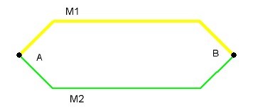
Picture 1.
The figure shows two dissimilar metal conductors M1 and M2, the ends of which at points A and B are simply welded together, although everywhere and everywhere these points are called junctions for some reason. By the way, many homemade handicraftsmen for homemade thermocouples, designed to work at not very high temperatures, use just soldering instead of welding.
Let's go back to Figure 1. If all this construction will simply lie on the table, then there will be no effect from it. If one of the junctions is heated with something, at least with a match, then an electric current will flow from the conductors M1 and M2 in a closed circuit. Let it be very weak, but still it will be.
To make sure of this, it is enough to break one wire in this electric circuit, and any one, and include a millivoltmeter in the resulting gap, preferably with a midpoint, as shown in Figures 2 and 3.
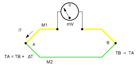
Figure 2
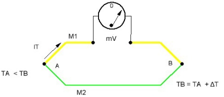
Figure 3
If now one of the junctions is heated, for example junction A, then the arrow of the device will deviate to the left side. In this case, the junction temperature A will be equal to TA = TB + ΔT. In this formula, ΔT = TA - TB is the temperature difference between the junctions A and B.
Figure 3 shows what happens if the junction B is heated. The arrow of the device deviates to the other side, and in both cases, the larger the temperature difference between the junctions, the greater the angle of the arrow of the device.
The described experience just illustrates the Seebeck effect, the meaning of which is that if the junctions of conductors A and B have different temperatures, then a thermoelectric power arises between them, the value of which is proportional to the difference in temperature of the junctions. Do not forget that it is the temperature difference, and not some temperature at all!
If both junctions have the same temperature, then there will be no thermopower in the circuit. In this case, the conductors can be at room temperature, heated to several hundred degrees, or they will be affected by a negative temperature - anyway, no thermoelectric power will be obtained.
What measures a thermocouple?
Suppose that one of the junctions, for example A, (usually called hot) was placed in a vessel with boiling water, and the other junction B (cold) remained at room temperature, for example, 25 ° C. It is 25 ° C in physics textbooks that is considered normal conditions.
The boiling point of water under normal conditions is 100 ° C, so the thermopower generated by the thermocouple will be proportional to the temperature difference of the junctions, which under these conditions will be only 100 -25 = 75 ° C. If the ambient temperature changes, then the measurement results will be more like the price of firewood than the temperature of boiling water. How to get the right results?
The conclusion suggests itself: you need to cool the cold junction to 0 ° C, thereby setting the lower reference point of the Celsius temperature scale. The easiest way to do this is by placing a cold junction of the thermocouple in a vessel with melting ice, because it is this temperature that is taken as 0 ° C. Then in the previous example everything will be correct: the temperature difference between the hot and cold junctions will be 100 - 0 = 100 ° C.
Of course, the solution is simple and correct, but each time to look for somewhere a vessel with melting ice and to keep it in this form for a long time, it is simply technically impossible. Therefore, instead of ice, various schemes for compensating the temperature of the cold junction are used.
Usually, semiconductor sensor measures the temperature in the cold junction area, and already the electronic circuit adds this result to the overall temperature value. Currently produced specialized thermocouple microcircuits having an integrated cold junction temperature compensation circuit.
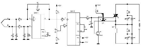
In some cases, to simplify the scheme as a whole, one can simply refuse compensation. Simple example temperature regulator for soldering iron: if the soldering iron is constantly in your hands, what prevents you from tightening the regulator a little, lowering or adding temperature? After all, he who knows how to solder sees the quality of soldering and makes decisions on time. The scheme of such a thermostat is quite simple and is shown in Figure 4.
Figure 4. Scheme of a simple thermostat (click on the picture to enlarge).
As can be seen from the figure, the circuit is quite simple and does not contain expensive specialized parts. It is based on the domestic K157UD2 microcircuit - a dual low-noise operational amplifier. On the DA1.1 op amp, the thermocouple signal amplifier itself is assembled. When using a TYPE K thermocouple when heated to 200 - 250 ° C, the output voltage of the amplifier reaches about 7 - 8V.
On the second half of the op-amp, a comparator is assembled, the inverting input of which is supplied with voltage from the output of the thermocouple amplifier. On the other - the reference voltage from the engine of the variable resistor R8.
As long as the voltage at the output of the thermocouple amplifier is less than the reference voltage, the positive voltage is held at the output of the comparator, so the trigger circuit works triac T1, made according to the blocking generator circuit on the transistor VT1. Therefore, the triac T1 opens and an electric current passes through the heater EK, which increases the voltage at the output of the thermocouple amplifier.
As soon as this voltage slightly exceeds the reference voltage, a negative level voltage appears at the output of the comparator. Therefore, the transistor VT1 is locked and the blocking generator stops generating control pulses, which leads to the closure of the triac T1, and cooling of the heating element. When the voltage at the output of the thermocouple amplifier becomes slightly less than the reference voltage. the entire heating cycle is repeated again.
To power such a temperature regulator, you need a low-power power supply with two polar voltages +12, -12 V. Transformer Tr1 is made on a ferrite ring of size K10 * 6 * 4 of ferrite НМ2000. All three windings contain 50 turns of PELSHO-0.1 wire.
Despite the simplicity of the circuit, it works reliably enough, and assembled from serviceable parts only requires a temperature setting that can be determined using at least a Chinese multimeter with a thermocouple.
Materials for the manufacture of thermocouples
As already mentioned, a thermocouple contains two electrodes made of dissimilar materials. In total, there are about a dozen thermocouples of various types, according to the international standard denoted by the letters of the Latin alphabet.
Each type has its own characteristics, which is mainly due to the materials of the electrodes.For example, the fairly common TYPE K thermocouple is made of a chromel - alumel pair. Its measurement range is 200 - 1200 ° C, the thermoelectric coefficient in the temperature range 0 - 1200 ° C is 35 - 32 μV / ° C, which indicates a certain non-linearity of the thermocouple characteristics.
When choosing a thermocouple, you should first of all be guided by the fact that in the measured temperature range the non-linearity of the characteristic would be minimal. Then the measurement error will not be so noticeable.
If the thermocouple is located at a considerable distance from the device, then the connection must be made using a special compensation wire. Such a wire is made of the same materials as the thermocouple itself, but, as a rule, is noticeably larger in diameter.
To work at higher temperatures, thermocouples made of precious metals based on platinum and platinum-rhodium alloys are often used. Such thermocouples are undoubtedly more expensive. Materials for thermocouple electrodes are manufactured according to standards. All the variety of thermocouples can be found in the corresponding tables in any good reference.
Read on in the next article - A few more types of temperature sensors: semiconductor sensors, sensors for microcontrollers
Boris Aladyshkin
See also at bgv.electricianexp.com
:

