Categories: Featured Articles » Home automation
Number of views: 37031
Comments on the article: 4
Design, configuration and use of the multifunction timer TE 15
In everyday life, we use many electrical mechanisms, the regularity of use of which suggests the automation of the process. For example, controlling outdoor lighting or a well pump. This idea is not new, and there are a lot of devices of this purpose, which have received a common name - a time relay.
The programmable weekly timer electronic TE 15 (Fig. 1) is a device that can control many household devices. He is a vivid example of the benefits of modern technology. To verify this, just remember what devices had to use before.
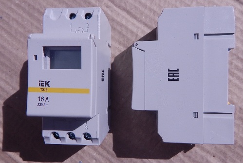
Figure 1. Digital timer - maximum functionality, nothing more
A bit of history
Previously, a mechanical timer was popular. Built-in to the outlet, it could turn on household appliances for a certain time (see. Fig. 2). In fact, it was a countdown timer; accordingly, its scope was limited.
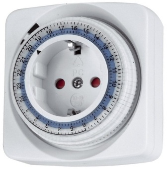
Figure 2. One of the works of Chinese industry - “Kitchen timer”
In fact, this is a regular outlet with a timer, the peak of popularity of such devices came in the mid 80s of the last century.
As time went on, gradually, mechanical devices were replaced by electromechanical ones, and, in turn, they were replaced by electronic ones, such as an electronic stopwatch.
The functionality of these devices has expanded significantly. Now it's the turn of digital devices, another year or two and smart home concept will make its own adjustments.
Let's get back to the topic of the article.
Design Features
Like any device of this type, TE 15 consists of the following structural elements:
-
small-sized switching power supply unit;
-
microprocessor and its electronic strapping;
-
informational LCD display;
-
interface control unit (buttons for programming);
-
relay connecting or disconnecting the load;
-
battery (it is necessary to save the settings if the power is turned off).
The presence of a programmable microprocessor allows you to set eight different cycles of programs that will control the load. This is done using the buttons installed on the front panel (Fig. 3).
The information display can operate in two modes: display the current time and be used when setting operating modes.
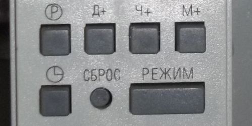
Figure 3. Control unit buttons
Customization
Detailed programming instructions, a manual, and a wiring diagram are included with the device. Therefore, we will consider this part briefly in order to recall the details.
Short programming guide
Algorithm of actions:
1. Apply power to the timer.
2. Press the “Reset” button (marked with a red oval in Figure 4).
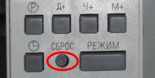
Figure 4. Reset button
3. Wait for the end of the status survey procedure (lasts about eight seconds), and a reverse report is turned on on the indicator.
4. Set the current time data and date. By default, the time is set in 24-hour mode, to switch to a 12-hour display, press the button above which the symbolic dial is shown (marked in Figure 5) and hold it in this state for at least five seconds. After this period, the display will show the choice between “AM” and “PM” (before noon or after). To switch back to 24-hour mode, press this button again.
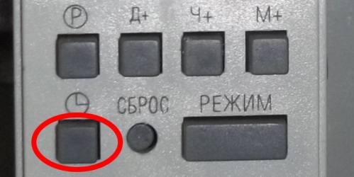
Figure 5. The time mode selection button is marked in red
5. Having selected the display mode, you should set the current time parameters. To do this, hold the button with the dial (see Fig. 5) and press “D +” (Fig. 6 is marked in red). Thus, the day of the week is selected.The designations “MO”, “TU”, “WE”, “TH”, “FR”, “SA”, “SU” are the English abbreviations for the days of the week by the first two letters, they correspond to Monday, Tuesday, Wednesday, Thursday, Friday, Saturday and Sunday.
The time is set using the “H +” and “M +” buttons (marked in green and blue in Figure 6), with which hours and minutes are set.
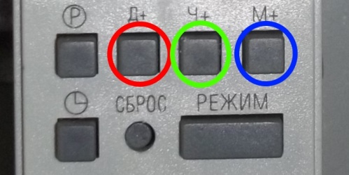
Figure 6. Buttons for setting the day of the week and time
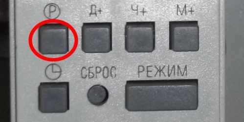
Figure 7. Cycle control button
After the date is set and the time is indicated, you can start programming. This is done as follows:
-
to set the first operation cycle, press the button indicated in Figure 7;
-
after that, select the day of the week using the “D +” button (shown in red in Figure 6);
-
then set the exact response time using the buttons "H +" and "M +";
-
press the control key shown in Figure 7 to complete the programming of this power cycle.
The management of the remaining cycles is done in the same way. If there is a need to disable any of the established operation modes, just press the control button (Fig. 7), select a cycle and turn on the “Mode” key.
This appliance can turn on or off the connected equipment. The choice of this option is carried out by the “Mode” button. At the same time, the status of the contacts will be displayed on the indicator: “Auto Off” “Auto On”, which corresponds to open or closed relay contacts.
Specifications and wiring diagram
The device is designed to be powered by a household electrical network, the permissible voltage range of which is from 180V to 264V, at a standard frequency of 50Hz. The integrated processor allows you to set up to eight on-off cycles, with a minimum time interval of at least one minute. The presence of a backup battery allows you to save current settings even when the device is disconnected from the network.
The internal relay of the device can switch the load with a current strength of up to 16A. The housing has a degree of protection IP20.
Permissible timer error is no more than two seconds per day, which is acceptable for devices of this class.
The presence of a backup battery allows you to save settings even when the device is disconnected from the network.
As for wear resistance, it depends on the manufacturer, for example, TDM Electric or EKF ensure that their products can withstand more than a million on-off cycles.
The device is equipped with a DIN rail mount, 35mm wide.
The dimensions of the timer are 82x36x66mm, and the weight is only 150 grams.
The device remains operational at an ambient temperature of -10 ° C to 40 ° C and a relative humidity of not more than 98%.
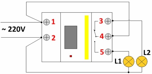
To properly connect the device, you should be guided by the circuit shown in Figure 8.
Figure 8. Load connection
As you can see, the connection principle is quite simple: voltage is applied to contacts “1” and “2”, the load is connected to contacts “3” and / or “5”. With the indicated connection method, the lamp L1 will be turned off, and L2 will be turned on. When the device works, the situation will change. L2 - turns off, L1 - lights up.
Application
If you use such a device, share in the comments to the article for what purposes it is used, this information may be useful to someone.
Dmitry Makarov
See also at bgv.electricianexp.com
:

