Categories: All about LEDs, Microcontroller circuits
Number of views: 21959
Comments on the article: 1
RGB LEDs: how they work, internal device, how to connect, RGB-led and Arduino
Multi-color LEDs, or as they are also called RGB, are used to indicate and create a backlight dynamically changing in color. In fact, there is nothing special about them, let's look at how they work and what RGB LEDs are.
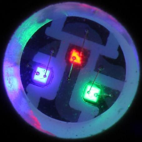
Internal organization
In fact, an RGB LED is three single-color crystals combined in one housing. The name RGB stands for Red - red, Green - green, Blue - blue according to the colors that each crystal emits.
These three colors are basic, and any color is formed on their mixing; this technology has long been used in television and photography. In the picture above, you can see the glow of each crystal individually.

In this picture you see the principle of mixing colors to get all the shades.
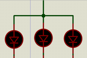
Crystals in RGB LEDs can be connected as follows:
- With a common anode;
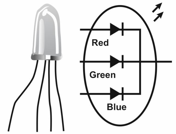
- With a common cathode;
- Not connected.
In the first two options, you will see that the LED has 4 outputs:
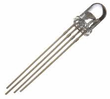
Or 6 conclusions in the latter case:
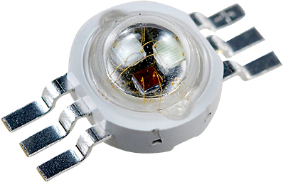
You can see in the photograph under the lens three crystals are clearly visible.
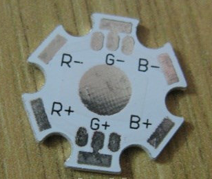
For such LEDs, special mounting platforms are sold, they even indicate the purpose of the terminals.
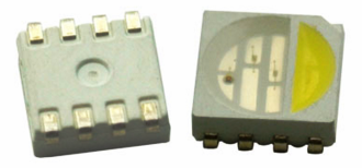
You can not ignore the RGBW - LEDs, their difference is that in their case there is another crystal emitting white light.
Naturally, it was not without tapes with such LEDs.
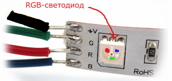
This picture shows a tape with RGB LEDs type SMD 5050collected according to the scheme with a common anode, the luminous intensity is adjusted by controlling the “-” (minus) of the power source.
To change the color of the RGB tape, special RGB controllers are used - devices for switching the voltage supplied to the tape.
Here is the RGB pinout of the SMD5050:
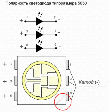
And there are no ribbons, there are no features for working with RGB ribbons, everything remains the same as with monochrome models.
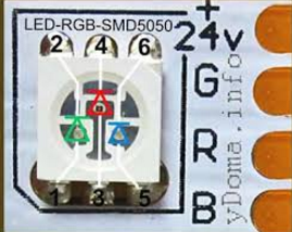
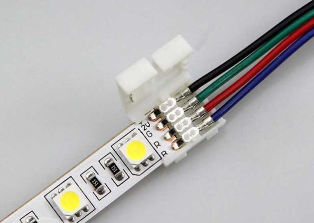
For them there are also connectors for connecting the LED strip without soldering.
Here is the pinout of the 5 mm RGB LED:
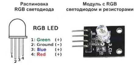
How does the color of the glow
Color adjustment is carried out by adjusting the brightness of the radiation of each of the crystals. We have already considered The way to adjust the brightness of the LEDs using a PWM controller.
The RGB controller for the tape works on the same principle, it has a microprocessor that controls the negative output of the power source - it connects and disconnects it from the circuit of the corresponding color. Usually, a remote control is included with the controller. Controllers come in different capacities, their size depends on this, starting from such a miniature one.
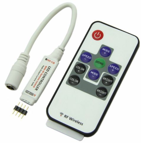
Yes, such a powerful device in a case the size of a power supply.

They connect to the tape in the following way:
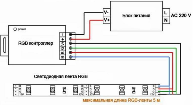
Since the cross-section of the tracks on the tape does not allow connecting the next segment of the tape in series with it, if the length of the first exceeds 5 m, you need to connect the second segment with wires directly from the RSL controller.
But you can get out of the situation and not pull the extra 4 wires 5 meters from the controller and use an RGB amplifier. For its operation, you need to extend only 2 wires (plus and minus 12V) or power another power supply from the nearest 220V source, as well as 4 "information" wires from the previous segment (R, G and B) they are needed to receive commands from the controller, so that the whole structure glows the same.
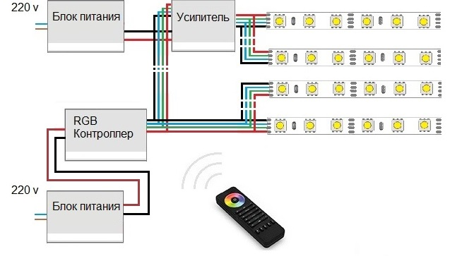
And the next segment is already connected to the amplifier, i.e. he uses the signal from the previous piece of tape. That is, you can power the tape from the amplifier, which will be located directly next to it, thereby saving money and time on laying wires from the primary RGB controller.
DIY RGB-LED
So, there are two options for controlling RGB LEDs:
1. Use three independent PWM controllers and manually adjust the brightness of each of the crystals.
2. Use a microcontroller with PWM outputs.
To control the LED with Arduino - use this diagram:
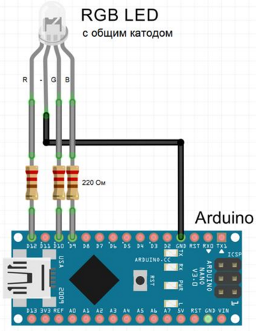
Pay attention to the findings of R, G and B at the LED are connected to PWM pins of Arduina.
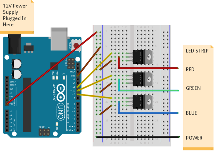
To control a powerful RGB tape, the circuit has no fundamental differences, except that it is connected to the microcontroller through amplifiers - transistors.
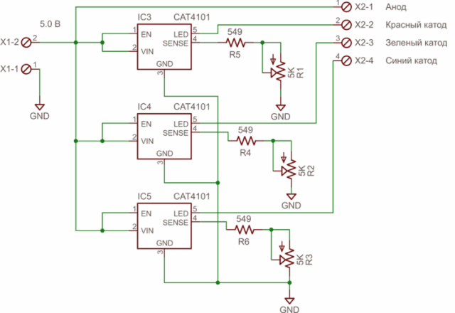
Here is a variant of the circuit without the use of arduin and other microcontrollers, with the help of three CAT4101 drivers, capable of generating currents up to 1A.
However, now the controllers are cheap enough and if you need to adjust the LED strip - it is better to purchase a ready-made version. Arduino circuits are much simpler, the more you can write a sketch with which you will either manually set the color, or the color search will be automatic in accordance with the specified algorithm.
Conclusion
RGB LEDs allow you to make interesting lighting effects used in interior design, as a backlight for household appliances, for the effect of expanding the TV screen. There are no special differences when working with them from conventional LEDs.
See also at bgv.electricianexp.com
:
