Categories: All about LEDs
Number of views: 63034
Comments on the article: 2
How to correctly calculate and choose a resistor for an LED
Each of us has seen Light-emitting diode. An ordinary small LED looks like a plastic cone-lens on conductive legs, inside of which there is a cathode and anode. In the diagram, the LED is depicted as a regular diode, from which the arrows indicate the emitted light. So the LED is used to receive light when electrons move from the cathode to the anode - pn junction visible light is emitted.
The invention of the LED occurred in the distant 1970s, when incandescent lamps were used to obtain light in all. But today, at the beginning of the 21st century, LEDs finally took the place of the most effective sources of electric light.
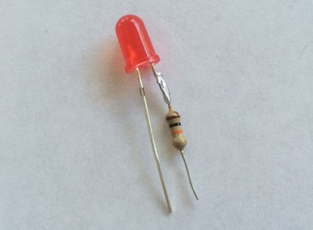
Where is the plus sign for the LED, and where is the minus sign?
To properly connect the LED to the power source, you must first observe the polarity. The anode of the LED is connected to the plus “+” of the power source, and the cathode to the minus “-”. The cathode connected to the minus has a short output, the anode, respectively, is long - the long leg of the LED is on the plus “+” of the power source.
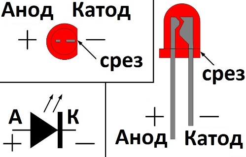
Look inside the LED: the large electrode is the cathode, it is to the minus, the small electrode, which looks just like the end of the leg, is the plus. And next to the cathode, the LED lens has a flat cut.
Do not hold the soldering iron for a long time
The LED leads should be soldered neatly and quickly, because the semiconductor junction is very afraid of excess heat, so you need to touch the soldering iron with short strokes of the soldering iron, and then take the soldering iron out of the way. It is better to hold the soldered LED leg with tweezers during the soldering process to ensure that heat is removed from the leg just in case.
Resistor required when checking LED
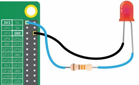
We come to the most important thing - how to connect the LED to a power source. If you want to check the LED for performance, then do not directly connect it to the battery or to the power supply. If your power supply is 12 volts, then use a 1 kOhm resistor in series with the LED under test for safety.
Do not forget about polarity - a long lead to a plus, a lead from a large internal electrode to a minus. If you do not use a resistor, the LED will quickly burn out, if you accidentally exceed the rated voltage, a large current will flow through the p-n junction, and the LED will almost immediately fail.
LED color
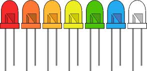
LEDs come in different colors, but the color of the glow is not always determined by the color of the LED lens. White, red, blue, orange, green or yellow - the lens can be transparent, and if you turn it on it will turn out to be red or blue. Blue and white LEDs are the most expensive. In general, the composition of a semiconductor affects the color of the glow of the LED, and the color of the lens as a secondary factor.
Multi-color RGB LEDs contain in one case several light emitting pn junctions, each of which gives its own glow color. By combining the brightness of the components with currents or current pulse frequencies (for red, green and blue crystals), you can get any shade. Here, of course, balancing resistors are needed for each color channel.
Find the resistor value for the LED
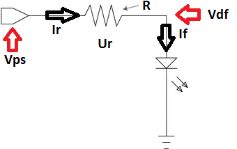
The resistor is connected in series with the LED. The function of the resistor is to limit the current, make it close to the nominal value of the LED so that the LED does not instantly burn out, and would work in normal nominal mode. We take into account the following initial data:
-
Vps is the voltage of the power source;
-
Vdf - direct voltage drop on the LED in normal mode;
-
If is the nominal current of the LED in normal light mode.
Now before you find the value of the required resistor R, note that the current in the serial circuit will be constant, the same in each element: the current If through the LED will be equal to the current Ir through the limiting resistor.
Therefore, Ir = If. But Ir = Ur / R - according to Ohm's law. And Ur = Vps-Vdf. Thus, R = Ur / Ir = (Vps-Vdf) / If.
That is, knowing the voltage of the power source, the voltage drop on the LED and its rated current, you can easily choose the appropriate limiting resistor.
If the found resistance value cannot be selected from the standard series of resistor ratings, then a resistor of a slightly larger value is taken, for example, instead of the found 460 Ohms, 470 Ohms are taken, which are always easy to find. The brightness of the LED will decrease very slightly.
Example of resistor selection:
Suppose there is a 12 volt power supply, and an LED that needs 1.5 volts and 10 mA for a normal glow. We select a quenching resistor. 12-1.5 = 10.5 volts should fall on the resistor, and the current in the serial circuit (power source, resistor, LED) should be 10 mA, therefore from Ohm's law: R = U / I = 10.5 / 0.010 = 1050 ohm. We select 1,1 kOhm.
What power should the resistor be? If R = 1100 Ohms, and the current is 0.01 A, then, according to the Joule-Lenz law, thermal energy Q = I * I * R = 0.11 J will be released every second on the resistor, which is equivalent to 0.11 W. A 0.125 W resistor will do, even a margin will remain.
LED series connection
If you have a goal to connect several LEDs into a single light source, it is best to perform the connection in series. This is necessary in order not to cling your resistor to each LED, in order to avoid unnecessary energy losses. LEDs of the same type, from the same batch, are most suitable for serial connection.
Suppose you need to consistently combine 8 LEDs of 1.4 volts with a current of 0.02 A to connect to a 12 volt power source. Obviously, the total current will be 0.02 A, but the total voltage will be 11.2 volts, therefore 0.8 volts at a current of 0.02 A should dissipate on the resistor. R = U / I = 0.8 / 0.02 = 40 Ohms. Choose a resistor at 43 ohms minimum power.
Parallel connection of LED strings is not the best option
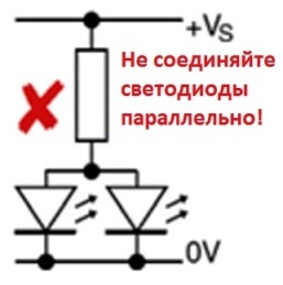
If you have a choice, it is best to connect LEDs in series, not in parallel. If you connect several LEDs in parallel through one common resistor, then due to the spread in the parameters of the LEDs, each of them will not be on an equal footing with the others, some will glow brighter, taking more current, and some will be dimmer on the contrary. As a result, any of the LEDs will burn earlier due to the rapid degradation of the crystal. It is better for parallel connection of LEDs, if there is no alternative, apply a limiting resistor to each circuit.
See also: Simple LED connection diagrams
See also at bgv.electricianexp.com
:
