Categories: Electric installation work
Number of views: 64812
Comments on the article: 0
How to connect a 380 volt outlet
 All electrical appliances consuming electricity are created by manufacturers according to state standards, when it is necessary to apply voltage to a motor windings, filaments of light sources, heaters and other actuators in a strictly defined way.
For this, a power cable is used, which is connected on one side to the terminals of the device, and on the opposite side, on a plug inserted into a socket so as to ensure the correct operation of the actuator.
For the same purpose, the contacts of the electrical outlet must be connected to the wiring, observing the established installation rules, and not arbitrarily. Even in a modern single-phase AC network, according to existing rules, three wires are used, and not two.
Earlier, in the electrical circuit with grounding, made according to the TN-C system, the arbitrary connection of phase and zero wires to the socket contacts created only inconvenience to the electrician, who is looking for damage, but did not affect the operation of the devices.
Now, improper connection of wires to a three-pin socket will lead to a change in the order of voltage supply, disruption of the actuator, and create a malfunction that causes an emergency.
380 Volt Three Phase Outlet Designs
Old plug and socket devices
In Soviet times, four-core electrical wiring consisting of three phases and one working zero was used inside a three-phase wiring of a 0.4 kV network. To connect electrical consumers, they created permanently installed sockets with recessed “mom” type contacts and plugs using protruding contact plates - “dad”.
On the body of the plug and socket, marking was made, indicating phase terminals and zero. Working zero is often shown with a standard ground icon.
Marking was performed both on the front side of the case, and from the back - where the wires are connected. It simplified installation, made it convenient to check the circuit during commissioning and operation.
Old plugs and sockets with four contacts now continue to work reliably in three-phase wiring diagrams assembled TN-C equipment grounding system. They can be successfully used in a modern five-wire circuit.
Modern designs
The transition to the new TN-S electrical grounding circuit and its modifications requires owners to connect three-phase electrical devices to work through five wires, four of which remain the same (three phases and zero), and an additional protective zero, or PE conductor, is added.
Therefore, they began to install five contacts on the plug and socket and mark them in the same way on both sides of each case.
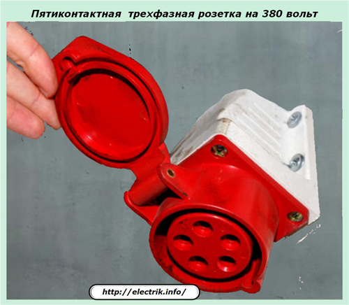
One of the modifications of the 380-volt three-phase outlet is shown in the photograph with the cover open.
Ways to connect wires to a power outlet
In modern designs, two methods are used:
1. using a screw mount;
2. screwless clamp.
First way
To connect the wires on the back of the case, a screw clamp is usually used when the end of the wire, cleaned from insulation, is inserted into the prepared socket and pressed in by the force of a screw.
This method has been used for a long time and has proven itself well. But, it takes a certain amount of time to cut the ends of the cable and screw tightening.
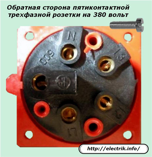
Contacts for connecting wires usually indicate:
-
phase ends - L1, L2, L3;
-
working zero - N;
-
protective PE conductor - standard grounding icon.
Second way
The screwless connection of the wires of three-phase electrical outlets is designed to save the time of electricians and allows to exclude some of their errors during operation. All operations are performed much faster, and with proper technology, the reliability of the connection is fully ensured.
The method of screwlessly connecting the wire to the socket contact of this design is shown in four photographs.
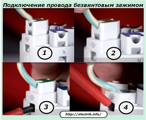
The first shot demonstrates that the insulation from the end of the wire is not removed during its preparation, it remains in place. To create electrical contact with the socket terminal, it will simply be pierced with a special built-in clip.
In the second photo, the wire is installed in the seat socket and is recessed down to the stop.
At the third stage, the wire is held in the previous position No. 2, and an ordinary screwdriver with a flat blade is inserted into the special groove of the socket.
Then, the handle of the screwdriver is simply lifted up, as shown in photo 4, and the design of the movable socket drops down into the socket. In this case, cutting through the insulation and clamping of the metal core.
The master only needs to remove the screwdriver, pull the end of the wire to make sure that it is firmly held inside the socket just in case.
Connection diagrams for three-phase 380 volt sockets
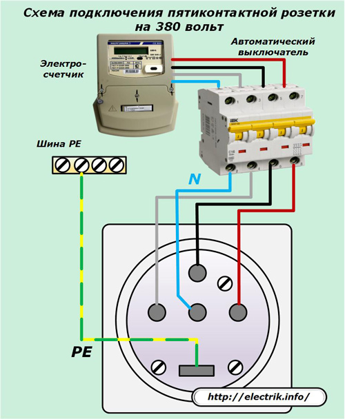
In order for the electric current from the voltage source of 0.4 kV to correctly come to the actuator of the three-phase electrical device, it is necessary to correctly connect the wires to the electrical outlet according to a certain scheme.
The principle that all consumed electricity is taken into account by the meter and passes through it is taken as its basis. Next, they mount the protection from a three-phase circuit breaker, which is designed to eliminate the effects of overloads in the network and the occurrence of short circuits.
Ways to connect five-pin sockets
The wires of the three phases and the working zero, through which the load currents from the switch pass, connect the sockets to their contacts.
For the correct and reliable operation of the circuit, a balance must be maintained between:
-
breaking capabilities of the circuit breaker;
-
load power generated by an electrical consumer;
-
thermal and current carrying capacity of the wires and the design of the socket with a plug;
-
dielectric strength insulation.
The fifth protective contact of the socket is connected via a separate PE conductor with a continuous connection to the PE bus of the building.
This is how a typical simplified circuit for connecting a three-phase five-pin 380-volt outlet works in modern electrical wiring. In many cases, it can be modernized, for example, when it is necessary to carry out some additional protection.
As an example, we consider the option of connecting an electrical device that requires increased safety from the possible occurrence of leakage currents through broken insulation on the housing.
In such cases apply RCD - a residual current device connected immediately after the power circuit breaker in front of the cable supplying the outlet. The machine will also protect the RCD.
Instead of two modular devices: a circuit breaker and an RCD, one design can be used: differential automaton, which simultaneously performs their functions. The connection diagram is shown below.
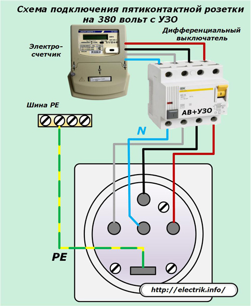
As you can see, the transition to it from the previous one is carried out only by replacing the circuit breaker with a differential one. No other actions are required to be performed, even all wiring remains laid by the previous method.
Ways to connect four-pin sockets
Models of old three-phase switching devices with four contacts can be quite normally operated in a modern five-wire circuit using the TN-S grounding system.
In this situation, ensuring the safety against leakage currents will have to be assigned to the PE conductor, which connects the PE main ground bus not to the protective contact of the outlet, which is absent, but connect it directly to the metal housing of the three-phase consumer, as shown in the figure below.
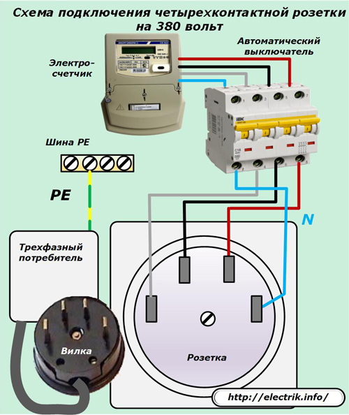
In this situation, a working electrical appliance must be installed permanently. It is difficult to operate mobile consumers safely with such a power scheme: it will be necessary to remount the PE conductor with each connection.
Methods for checking the installation of a three-phase 380 volt outlet
Having assembled any electrical circuit before putting it into operation, you always need to make sure that there are no installation errors, the voltage is supplied correctly, strictly according to the design.
In most cases, for many machine tools, phase wires to the socket and plug can be connected arbitrarily, but not to the terminals of the working or protective zero. This can only affect the direction of rotation of the three-phase electric motor: the alternation of the phases of the currents flowing along the working windings of the stator will change.
To correct such a case, it is enough to swap places - reconnect any two convenient phase wires to each other. Then the engine will rotate in the right direction. The same technique is used by magnetic starters that reverse the electric motor.
But it is forbidden to interchange the working and protective zero, in no case: the protection work and the safety of using the electrical installation will be violated.
After installing the electrical circuit to power a three-phase outlet, they immediately perform:
-
external inspection of all assembled chains and the reliability of the created contacts;
-
electrical measurements of the insulation resistance of the cores between themselves and on the housing.
Dielectric strength allows you to evaluate megaohmmeter. When it is not at hand, and the work requires quick completion, then the experienced craftsman can trust the proven protections - RCDs and circuit breakers, which should work if installed incorrectly and eliminate the consequences of errors.
But, before applying voltage, it is still necessary to carry out electrical measurements of the resistance of the assembled circuits with at least an ohmmeter or a tester switched to this mode, naturally, with the input circuit breaker turned off.
This operation is carried out in four stages in the following sequence:
1. one probe of an ohmmeter with a crocodile-type clamp is installed on the protective contact of the outlet, and the second pass through the rest of its contacts sequentially and take readings of the device;
2. The crocodile is transferred to working zero, and the resistance between the phase contacts is measured with a free probe;
3. The crocodile is transferred to any phase terminal, and with a probe they measure successively the resistance of the two remaining;
4. crocodile and probe measure the resistance between the last two phases.
In all cases, the arrow of the device should indicate infinity - ∞. A lower value will indicate a violation of insulation, the possibility of creating a short circuit. You have to look for the cause and eliminate it.
Only after observing this condition can the circuit breaker be turned on to supply voltage to the outlet, which will need to be analyzed.
Schemes for checking voltage on a three-phase 380-volt outlet
To assess the quality of power, we use an AC voltmeter or a multimeter switched to its mode.
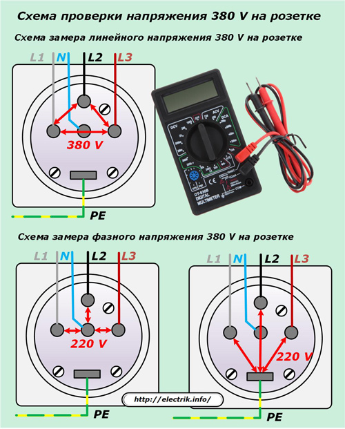
Between all phase contacts, we should see a symmetrical voltage of 380 volts, and between the working and then protective zero with phases - 220.
Only in this case, it is allowed to use the outlet to power consumers. However, you should pay attention to the serviceability of the connected three-phase devices. After all, they, too, can be with structural defects leading to an emergency.
Schemes for checking the correct connection of a three-phase plug to an electrical device
Before applying power to the appliance, its serviceability can be estimated by measuring the active component of the impedance at the terminals of the plug. A simple wiring diagram is designed to help understand these measurements.
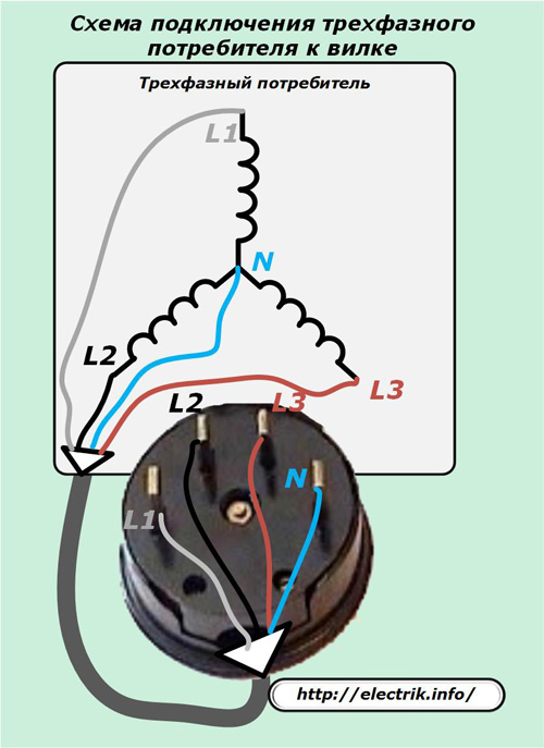
The active resistance of the wires of each winding should be the same, equal to a certain number. Denote it by the index R. This value we must see between the contact of the working zero and each phase.
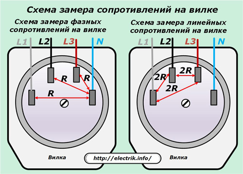
After this, it remains to verify that the series connection of the two windings, measured at the phase contacts, will be doubled - 2R.
This simple way will allow you to confidently connect the plug to the outlet.
Concluding the presentation of the material, I would like to recall that the socket and plug are designed for reliable operation when passing or stopping the rated current only after they are connected. It is impossible to break the passing load with their contacts: they are not intended for these purposes. After all, when the circuit is disconnected, a spark or electric arc arises, which must be extinguished.
Such a function is assigned to the special design of the power contacts of the circuit breaker. Only it is designed to disconnect load currents and even emergency situations.
See also at bgv.electricianexp.com
:
