Categories: Energy saving, Programmable controllers
Number of views: 10778
Comments on the article: 0
Classroom lighting automation
Energy saving is an activity (practical, scientific, organizational, informational) aimed at the rational and economical use of transformed and primary energy and natural energy resources.
A significant part of the organization’s costs in the field of housing and communal services are electricity costs. Let's look at an example of how you can organize one of the measures to save electricity by automating lighting control in classrooms.
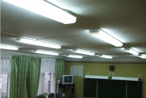
Modern lighting control systems allow you to create optimal conditions for the stay, the presence of people, as well as significantly save energy.
A very common situation - students and teachers, having spent a lesson in the classroom, constantly forget to turn off the lights after leaving. This raises the problem - how to make sure that after the last person leaves the classroom, the light turns off itself?

The aim of our work was to create a computer model of an automated lighting control system in the classroom, which saves energy.
In the development, a computer simulation method was used. We have designed an automatic lighting control system in the classroom, which, when there are people in the classroom, automatically turns on the light, and when the last person leaves the room, turns it off.
To do this, at the entrance to the classroom at a short distance from each other, two discrete motion sensors must be installed: one outside, the other inside the room. The sensor is triggered when a person enters the zone of his action.
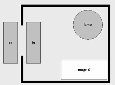
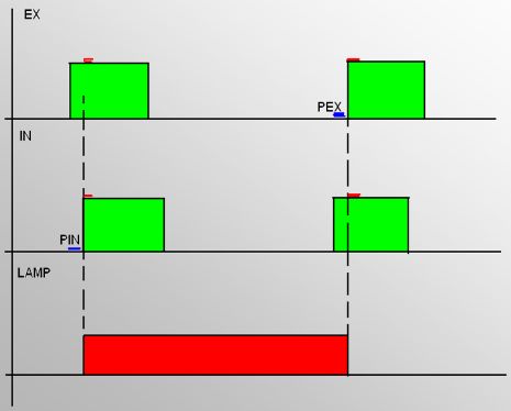
When the external sensor is triggered, then the internal one, it means that a person has entered the room. When the internal sensor is triggered, then the external one, it means that the person has left the room.
It is necessary to consider the number of people in the room. If a person entered, turn on the light; if a person exited, turn off the light. As long as at least one person remains in the room, the light must be on.
To create an automatic lighting control system, the PLC 150 controller from OVEN was used. This is a one-piece controller with discrete and analog inputs / outputs on board for automation of small systems. The PLC150 is equipped with 6 discrete 4 universal analog inputs, 4 relay outputs and 2 analog outputs. It has Ethernet, RS-232, RS-485 interfaces.
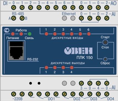
With this device, you can automate the lighting of almost any complexity. At the same time, intermediate contacts are not needed, switching of electric circuits occurs using built-in electromagnetic relays. For switching lighting circuits, it is necessary to use magnetic starters (one starter per circuit). The coil of each starter is connected to the relay outputs of the PLC.
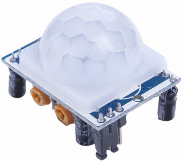
In addition to the controller, the automation circuit uses 2 HC-SR501 motion sensors. These output motion sensors give a logical unit if someone is moving and zero if there is no movement. When each motion sensor is triggered, a unit will be sent to one of the PLC relay inputs.
The creation of the work algorithm begins with the download of the CoDeSys program. It is free and is included with the PLC. CoDeSys implements several methods (languages) for developing an algorithm according to the international standard IEC 61131.
The final program written in CoDeSys is shown in the figure.
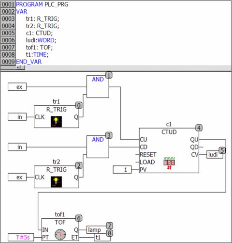
Classroom automation program
The program we created uses 2 R-flip-flops, two AND, a CTUD counter and a TOF timer.
The R_TRIG function block generates a pulse on the rising edge of the input signal.
Output Q is FALSE as long as input CLK is FALSE. As soon as the CLK gets TRUE, Q is set to TRUE.The next time the function block is called, the output is reset to FALSE. Thus, the block gives out a single impulse at each CLK transition from FALSE to TRUE.
AND - logical operation I. The result of the logical operation AND will be 1 if a and b are 1, and in all other (other) cases, the result will be 0.
CTUD is a reversible counter. This function block is used to count down and up. The signal "1" at the input R causes the assignment of the value "0" to the output CV. The signal "1" at the input LD causes the assignment of a value at the input PV to the output CV. At each transition from "0" to "1" at the input CU, the CV value increases by 1. At each transition from "0" to "1" at the input CD, the CV value decreases by 1.
TOF - function block ‘off-delay timer’. It provides a time delay before turning off the lights after leaving the last person from the classroom.
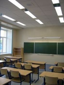 In addition, a photo relay can be added to the circuit, which automatically turns on and off the lighting, depending on the lighting conditions. The contact of the photo relay must be made to one of the relay inputs of the PLC and in the program, before the timer, put another AND element (AND) - one of the inputs of which will be a logical unit with the photo relay.
In this case, the light in the room will turn on only if there are people in the room and it becomes dark in the classroom.
As a result of the study, an electrical circuit diagram of the lighting system was developed, a program was written, and a computer model of the lighting system in the classroom was created.
Our automated lighting control system in the classroom will significantly save electrical energy, and thanks to its work, the service life of the lamps themselves increases.
See also at bgv.electricianexp.com
:
