Categories: How does it work
Number of views: 8930
Comments on the article: 0
How are amplifiers for TV antennas arranged and which one to choose
Any signal that is transmitted wirelessly may attenuate due to various obstacles in its path and other factors. In this regard, interference appears that especially affects analog communication. To ensure stable television reception, TV antenna signal amplifiers.

What affects the quality of television reception
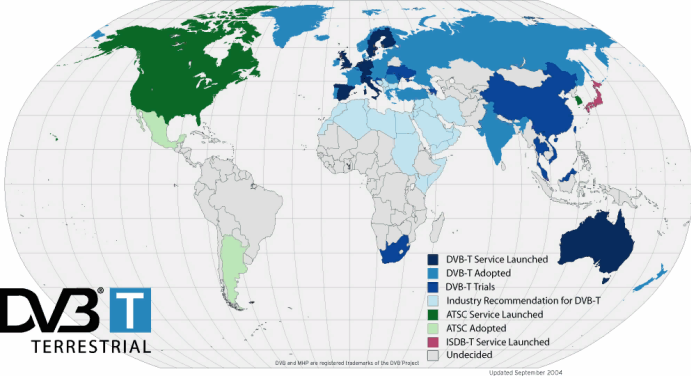
The television signal is transmitted mainly in the decimeter range (the so-called UHF). He can be analog or digital. Analog TV is fading away every year, and broadcasters and consumers increasingly prefer a digital signal. It is more resistant to interference and allows you to transfer a picture of better quality. Digital cable and terrestrial television standards are labeled DVB-T or DVB-T2.
The signal quality is determined by the level of reception at the consumer, measured in decibels dB (dB). A repeater is what the people call a television tower. And the farther the repeater is from the receiver (TV), the lower will be the signal level of the latter.
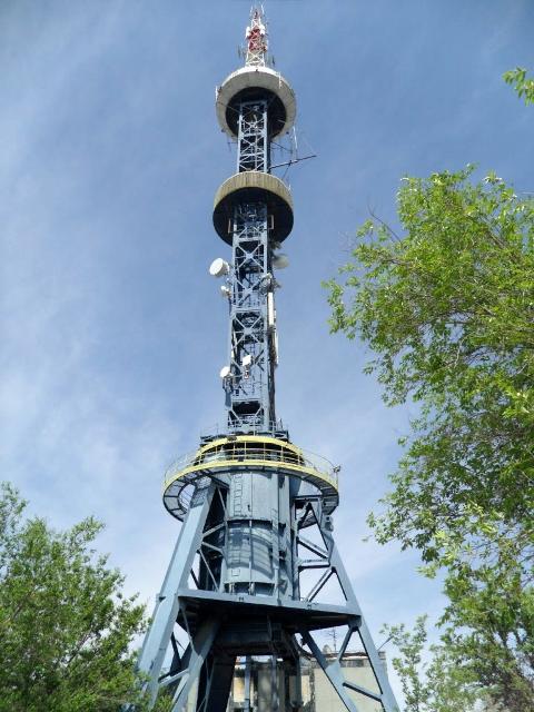
In addition to range, the quality of reception is affected by the presence of natural (trees, hills, mountains) and artificial (buildings, metal structures) obstacles located between the repeater and the receiver.
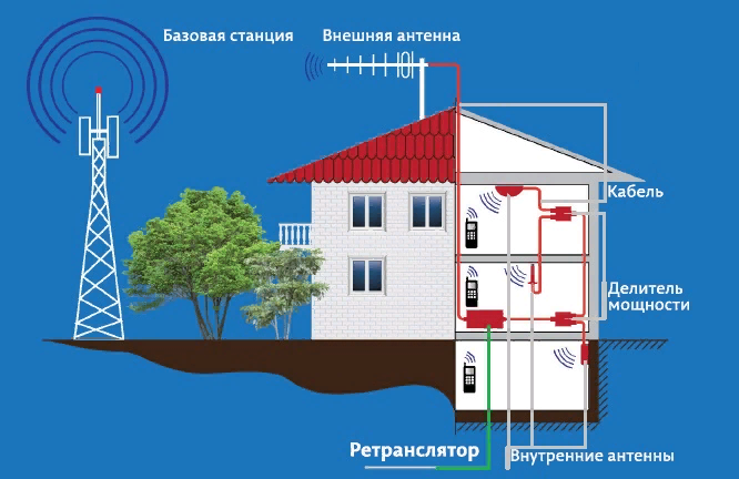
In the ideal case, the repeater should be in direct line of sight from the receiving antenna, while at a certain elevation. But this situation rarely happens. The antenna itself should be directed towards that repeater whose visibility is better, and the distance closer, to ensure the highest possible reception level. This is shown below on the example of receiving telephone communications.
Interesting:
Even with the ideal location of the receiver and transmitter antennas, the weather also affects the quality of the connection - in bad weather the signal will be lower.
Also, the signal quality is affected not so much by the location of the antennas, but by the quality of the cable, the presence of splitters and couplings.
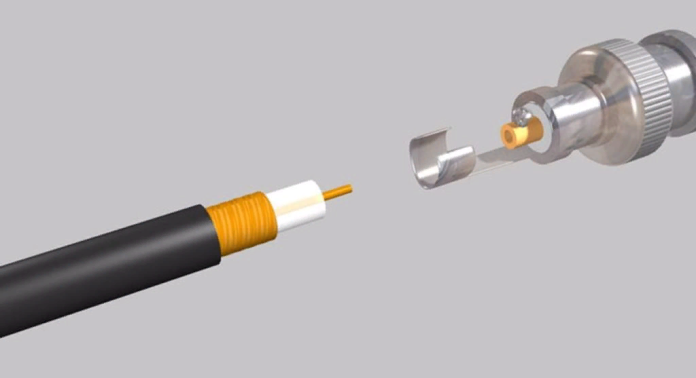
In the best case, one receiver should be connected to the antenna with an indissoluble coaxial cable with the corresponding impedance.
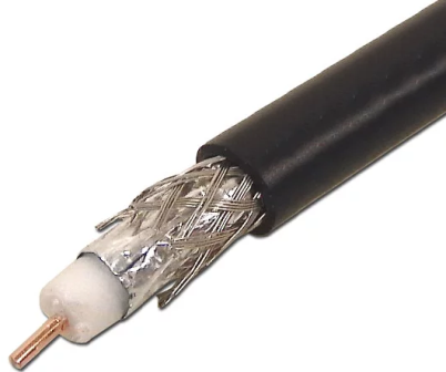
Noise sources
In addition to obstacles, noise sources also contribute to the signal. These include radio transmitting devices that operate at an adjacent frequency as well as interference introduced by the influence of electrical networks. For example, when operating devices that fill the network with various harmonics, this is a variety of collector motors, and fluorescent lamps with electromagnetic power circuit, and microwaves and other devices.
Types of Amplifiers
Amplifiers are distinguished by the range of the amplified signal:
-
Broadband - include several ranges. On this positive qualities end. Unable to achieve uniform gain at a large number of frequencies.
-
Band - designed for a specific frequency band.
-
Multi-range - cascades are built into them for receiving and mixing signals from different ranges, sometimes with the possibility of independently adjusting the gain.
Also, household tv signal amplifiers are distinguished by supply voltage:
5V - such amplifiers can receive power via a coaxial cable directly from a TV or TV tuner, this is the voltage provided in most devices. But antennas with such amplifiers have gained distribution relatively recently. Moreover, such amplifiers are most often installed directly in the antenna.
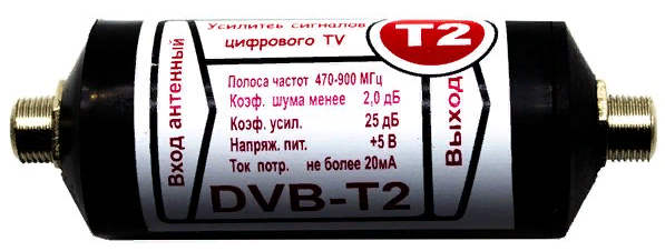
12V - a more common option. They use an additional power supply unit sometimes with voltage adjustment (for adjusting the reception level, this is a relatively useful option).

Distinguish antenna amplifiers and performance:
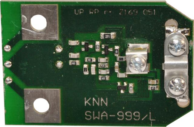
On pcb - are installed in a box located directly on the antenna. Their disadvantage is that the cable length and the number of connections from the antenna to the TV reduce the signal level.
Remote - either in the form of a separate stationary device (a small unit resembling the dimensions of a TV tuner), or in the form of a small box that is installed directly on the cable. In any case, the amplifier is connected on the line between the antenna and the TV.

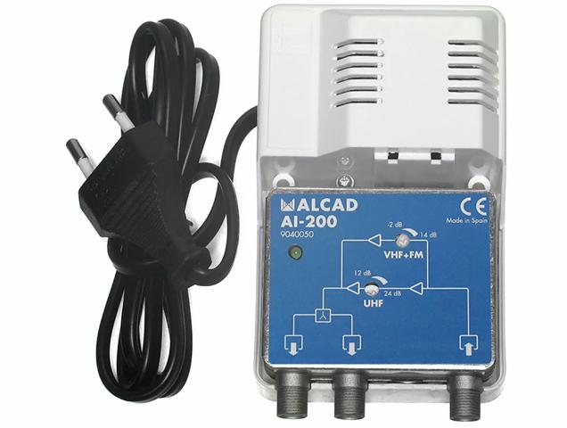
A more detailed classification of amplifiers for TV antennas can be given, but for the average tasks, the information given is sufficient.
Schemes
The main characteristics of any amplifier is the gain and noise level. For a radio signal, the amplifier must be designed for the frequencies of the required range. And most often, the narrower the frequency band, the better the gain.
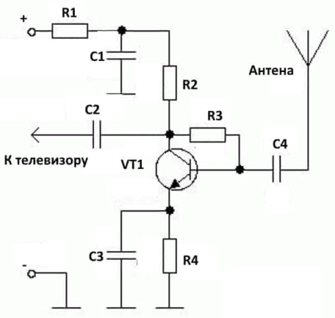
In a generalized version, the amplifier circuit is the same circuit that we modeled in an article on bipolar transistors. But it provides requirements for the operating frequency of the transistors used. Schemes can consist of one or more cascades. Single-stage circuits are simple and unpretentious in tuning, but have a weak gain.
The figure below is an example of a single-cycle antenna amplifier. As a transistor, a domestic KT368 or its foreign analog 2N918 can be used.
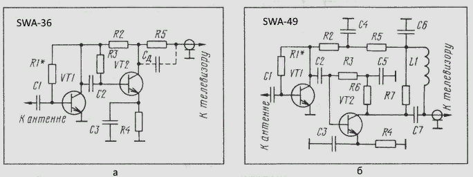
While Ku can be increased arbitrarily strongly by adding additional cascades. But with an increase in the number of cascades, the level of interference can also increase if actions are not taken to combat them in the form of various filters, proper PCB layout and the mandatory use of low-noise transistors and other electronic components. The figure below shows the diagrams of the popular two-stage broadband amplifiers of the SWA series.
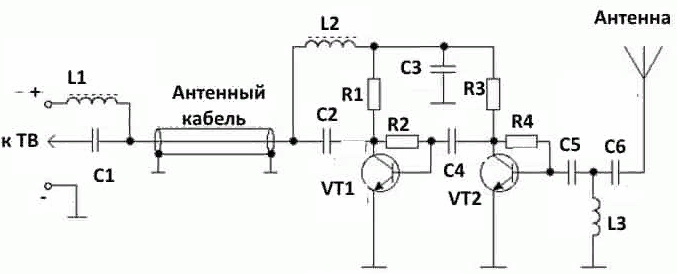
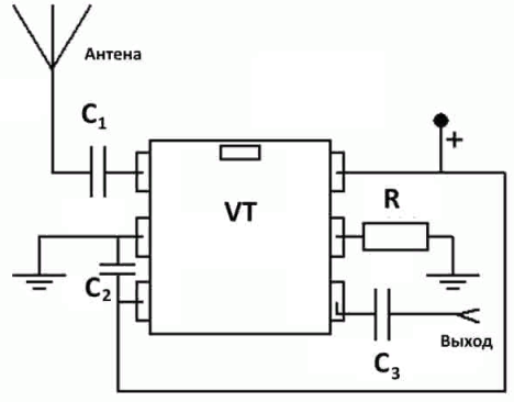
The modern element base allows you to build amplifiers on the basis of integrated circuits, which eliminates the need for complex device settings, which can be accurately done without oscilloscope difficult.
In addition, all discrete components have a strong variation in parameters, for example, the once popular, but already outdated (although used by ham radio to this day) series of KT315 transistors in some modifications had a spread in gain of more than 10 times.
Think about it, two identical transistors could amplify with such a difference. Naturally, such a spread was reduced in modern industry and more accurate operations were carried out to produce semiconductor crystals of the desired structure.
Integrated circuits are good in that all the transistors included in their composition are etched on a single chip and have approximately the same parameters.
The choice
When buying an amplifier for a TV signal, you can not be guided by the principle the more - the better. Therefore, there is a logical question of what to look for when choosing an amplifier for a TV antenna? Let's figure it out!
Excessive amplification of the signal will lead to its distortion, sometimes it is called overload or clipping. Therefore, the amplifier is selected based on the source data on the real level of reception and the desired gain. In general, this can be reduced to determining the distance to the repeater.
It will also be good if the amplifier provides for tuning or wide adjustment of the gain - these models are much more versatile.
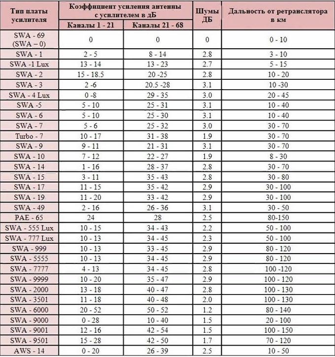
Next, you need to determine which range you need to strengthen in the performance of the device itself. The table above shows the technical characteristics of popular amplifiers for trellised antennas (popularly called “polka”).
See also at bgv.electricianexp.com
:
