Categories: How does it work
Number of views: 45594
Comments on the article: 1
How the electric heat-insulated floor is arranged and works
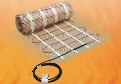 The desire of a person to create comfortable living conditions has led to the development of various heating systems. Among them, recently, structures mounted on the floor and working at the expense of electricity have become increasingly popular.
Types of electric underfloor heating
Manufacturers produce various modifications that can be arbitrarily combined as a heating element:
1. cable heating;
2. heating mats;
3. film infrared emitter;
4. liquid-electric constructions.
Physical principles laid down in the work of electric underfloor heating
Resistive cable heating
When electricity is transferred based on the Joule-Lenz law, heat is released. This pattern is the basis for the operation of heating elements.
If metals and their cross-section are selected in ordinary wires in order to reduce heat loss at maximum load, then structures are created in the heat-insulated floor system that are capable of emitting the maximum amount of heat energy for a long time without violating performance characteristics.
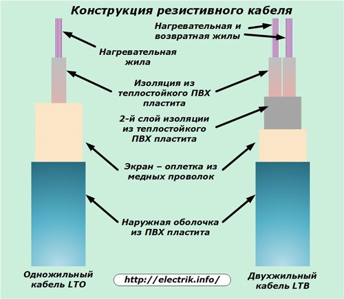
For this, heating elements are created in the form of cable structures consisting of:
-
conductive wire of a resistive type that generates heat;
-
a layer of Teflon insulation made of heat-resistant PVC plastic.
Such cables can be made with one internal conductive core or two. They are used for various installation and connection methods. Manufacturers give them a guarantee of 20 years or more, subject to operating rules.
The two-core cable has an additional layer of insulation located between the screen braid of a thin copper wire and a dielectric heat-resistant coating of cores. One of the cores has the function of a heating element, and the second, as a simple conductive, is placed parallel to the first. Such their location significantly reduces the level of radiation of the electromagnetic field and its effect on the environment.
A typical resistive cable design is shown in the picture.
During the operation of these structures, the balance of heat generated from the electric current passing through the veins and its removal to the heated floor must be observed. To do this, all areas of the floor adjacent to the cable are created with a uniform structure that provides uniform thermal and mechanical loads.
The resistive cable is poured with a cement-sand screed of a certain thickness, which can be additionally covered with a layer of ceramic tile, laminate or other floor materials.
Cables with wires of self-regulating heating
In the underfloor heating system, self-regulating heating cable designs can be used. They have ordinary conductive, but not heating conductors, between which there is a semiconductor matrix with a huge number of independent elements. Its dielectric properties are determined precisely by these semiconductors that respond to changes in their ambient temperature.
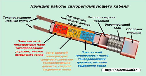
When a section of the self-regulating cable is cooled, a structure with a large number of tracks is created inside the matrix due to semiconductors for the current to pass through them, which heats the cable and its surrounding layers.
At an average temperature, the structure of semiconductors increases the electrical resistance, reducing the conditions for the flow of current through them and, thereby, somewhat reduces heat generation.
If any part of the cable is very hot, then the number of tracks for the passage of current in it is sharply limited, reducing its electrical conductivity.
In this way, the temperature of the heating of the environment is regulated even without a thermostat and temperature sensors. Self-regulating cables are more convenient to use because they do not need to create a homogeneous structure for heat transfer, like their resistive analogues. Their individual sections can be subjected to various temperature loads.
Read more about this type of cable here: The use of self-regulating heating cables
Cable mats
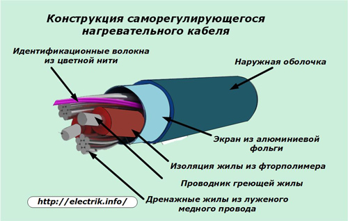
Initially, resistive cables when installing a warm floor were simply laid out on the floor in the form of a snake, and then fixed with fasteners. This technology is used now for single-core and two-core structures.
However, manufacturers began to produce cable mats. An example of such a design is shown in the picture, where the cable itself is already woven into a soft dielectric grid in a certain way. It no longer needs to be laid out carefully. Simply roll the folded roll along the length of the room for subsequent fixation with a solution.
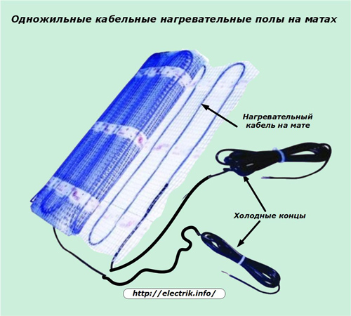
Cold ends for connecting a cable mat to the electrical circuit are included in the package. They are connected through special adapter couplings. Direct connection is prohibited by installation technology.
If there is a need to rotate the direction of the layout, then the fastening grid can be easily cut with ordinary scissors without touching the cable, which then simply unfolds in the right direction at any angle.
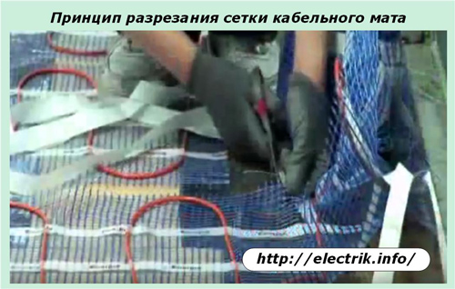
In this way, the layout of the mat in any room in an even layer is facilitated. At the same time, it is easier to avoid overlapping of individual cable sections with each other.
Film infrared floor heating
This technology is based on the use of infrared raysemanating from thin heating elements through which an electric current is passed.
They are made with carbon strips located between two layers of a special film. Carbon (carbon fiber) is applied by nano-spraying with a layer thickness measured to one micron, and is insulated on both sides with a thin but very strong polymer film with high dielectric properties.
Carbon strips are connected to copper buses, which serve as conductors for supplying voltage.
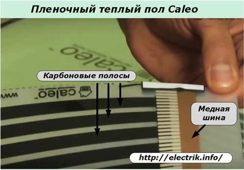
The heating carried out by infrared rays from the warm floor, by its nature, is no different from the natural heating by the light of the sun. Only the floor temperature is brought to 30 ÷ 35 degrees and is sent from the bottom up.
Liquid Electric Structures
Electro-water developments of a warm floor combine the electric heating of filaments with the subsequent transfer of heat through a coolant - water, located in a sealed plastic tube with high-strength mechanical characteristics.
The whole structure is assembled in the form of a seven-core cable using alloys for chrome and nickel threads and a sheath coated with silicone and teflon.
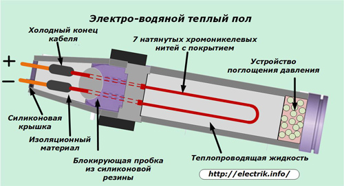
The silicone layer withstands temperatures up to 280 degrees, having high dielectric properties. Teflon coating creates an obstacle to the penetration of water and is highly resistant to chemicals.
The liquid that fills the cable can successfully withstand even twenty-degree frost without freezing, but it boils quickly when passing electric current through the threads. During its boiling, heat is transferred to the environment faster. It provides energy saving.
The heat transfer from the heating filaments to the boiling liquid and further to the warm floor environment protects the nickel-chromium alloy from overheating, protects it from burnout, and allows it to operate for a long time.
Since an increased gas pressure is created during boiling of the liquid inside the sealed enclosure, a special absorption system is used to reduce it, reducing this effect and ensuring safe operation.
Tubular cable bodies made of structured mesh polyethylene have:
-
resistance to cooling at low temperatures;
-
resistance to cracking;
-
high impact strength.
The design and composition of electric underfloor heating
The room to be heated must be protected from constant drafts and heat leaks. For this, all heating elements are mounted only on a thermal insulation layer, which prevents energy losses due to heating of floor slabs and escape to the atmosphere.
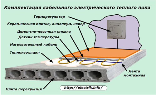
The heating cable, made according to one of the above schemes, is located on the insulating layer, fastened with a mounting tape. Inside his snake at the same distance between the turns, a corrugated tube is laid out with a temperature sensor placed in it, which will monitor the degree of floor heating.
This tube is hermetically sealed at one end. It is intended not only to accommodate the temperature sensor, but also for the possibility of convenient replacement in the event of a breakdown.
All installed heating elements together with this tube will be filled with a cement-sand screed. Its thickness depends on the design of the cable and must be carefully performed in an even layer. Voids are not allowed. Ceramic tiles are glued on top or other flooring is mounted.
At a convenient height for the wall of the room is located temperature controller, which controls the operation of the warm floor in automatic mode. When connecting it, you will need to bring wires from:
-
power supply cable;
-
heating elements;
-
temperature sensor.
To perform covert wiring, it is necessary to provide cable channels or to wall the walls.
Schemes for connecting floor heating elements to electrical wiring
It is important to remember that the installation and assembly of the circuit should be completed by checking the operation of electrical equipment under voltage before filling the heating cables with fixing solution. At this point, it’s easier to troubleshoot.
Re-inclusion in the work will be performed after the solution solidifies completely in a month. Previously, the cable tie will not harden and the cable will be damaged.
An example of connecting a warm floor, which includes two sets of heating cables and one thermostat with a sensor, is shown in the picture.
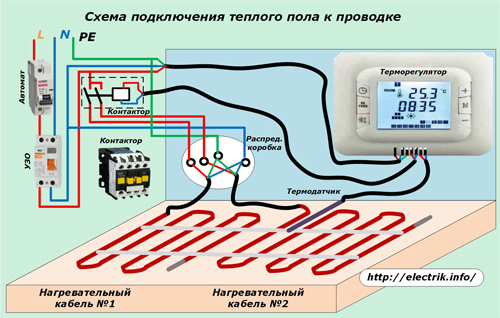
In the electrical panel from the circuit breaker, an RCD is connected. It protects the entire circuit from possible leakage currents through electrical enclosures that are tied PE conductor.
The temperature sensor is connected by a cable to a temperature controller, which is connected to power circuits via an RCD and, at the same time, controls the contactor through a separate cable. The contactor output circuits are connected to the heating elements using a junction box.
The inclusion of a contactor in the circuit allows you to simultaneously control the operation of several heating sections and reduce the load on the electrical circuits of the thermostat.
The simplest thermostats of mechanical or electrical type allow you to set only the temperature limits of regulation of heating of the floor covering.
More sophisticated electronically controlled models have the ability to use a time-based weekly schedule for the operation of heaters at a user-defined time of day. Due to this, the energy consumption for floor heating is reduced when the owners are absent in the apartment.
Recommendations for the selection, installation and operation of underfloor heating
Flooring selection
Manufacturers recommend using the following as a topcoat on a cement-sand screed:
-
a natural stone;
-
ceramic tile;
-
porcelain tile.
They best transfer heat through themselves to the room. The use of wood, parquet, laminate and other materials is also allowed. However, they have worse heat transfer and can reduce the effect of heating.
Coating deformation
Heating elements create temperature differences at which the floor covering slightly changes its size. To avoid its deformations, you should create small gaps for the laminate elements. You can not close it to the walls and fasten it to the baseboard. When exposed to heat, the floor should expand freely and remain completely flat.
Floor insulation
The choice of material for it allows the rational use of electricity, since it affects heat loss. In order to create comfortable heating, foil insulation is used, consisting of foamed polymeric materials with a layer thickness of 3 to 10 mm. Its use saves electricity from 10 to 20%.
The use of solid grades of expanded polystyrene with a layer thickness of 3 cm and a foil coated with a polymer can reduce losses by up to 30%.
Electricity consumption
The efficiency of any electrical structure is determined by the amount of energy expended on it. In order for the underfloor heating system to satisfy your needs, determine the tasks for it, which may be:
-
constant heating of the room;
-
floor heating only in the morning and in the evening when the owner is at home;
-
maintaining a stable temperature in the daytime for a comfortable stay on the floor of young children;
-
any other conditions.
Determine the area of the room and calculate the approximate cost of electricity for 1 hour of its operation or day, week, month. To do this, you can use the average operation data of the resistive heating cable to create comfortable conditions:
-
in dry rooms, 120 W per 1 m2 is consumed;
-
in wet rooms - 140 W per 1 m2.
For example, a 2 by 3 meter room in one hour of underfloor heating will consume 2x3x0.12 = 0.72 kW. With continuous operation for 10 hours, the energy consumption will be 7.2 kW.
The consumption of electricity for a film infrared floor and water-electric is a bit more economical.
Maintainability
Although manufacturers guarantee long-term operation of the warm floor, it is best to foresee the occurrence of breakdowns of individual parts and the elimination of their replacement at the project stage. To do this, the methods of connecting a temperature sensor with a thermostat should exclude the opening of a dried cement-sand floor screed when it becomes necessary to repair them.
Replacing the film on the infrared floor should not create unresolved issues with complex disassembly of the floor covering.
For liquid-electric modules, the replacement of the liquid and the heating element can be performed through a special mounting box. It is mounted on the finish line of the floor screed. And in case of violation of the integrity of the pipe, a small amount of leaked liquid will indicate the place of damage. It is simply cut out after opening. Then put the couplings and connect the two-way fitting.
See also at bgv.electricianexp.com
:
