Categories: Electrical connection of equipment
Number of views: 68638
Comments on the article: 1
How to connect a doorbell
Apartment owners are sometimes faced with the need to repair a doorbell or install its new model. To do this, they need to clearly know the electrical circuit of its connection and the principle of operation.
The calls by which the guest warns the owner of their arrival are divided into:
1. wired;
2. wireless.
Types of Wired Calls
Such designs are the most common and known. Among them, first appeared electromechanical modelswhich began to be installed on the homes of noble people from the second half of the 18th century. They continue to work with small improvements to this day.
After the start of industrial development of semiconductor elements began to be produced doorbells on electronic circuitse. They have the same type of bell ringing replaced with more diverse and melodic sounds that can be adjusted for duration, volume and other parameters.
The appearance of such a doorbell forty years ago is shown in the picture.
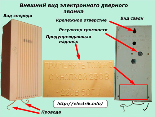
Two wires come out of the decorative plastic case, which are connected to the power circuit of the household network. On the back of the case are:
-
mounting hole;
-
volume control;
-
sealed screw securing the cover;
-
warning labels.
On such calls, not only the network parameters (≈220V, 50Hz) were indicated earlier, but also the type of button is 250 volts, not lower. This is dictated by safety rules.
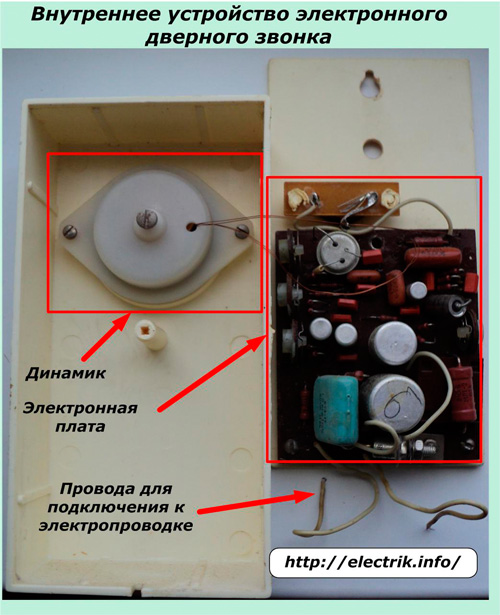
Inside the case there is a speaker and a getinax board with electronic components.
Typical Door Bell Connection Diagram
Electromechanical and electronic wire models are connected to the power supply according to a single principle: when voltage is applied to the input terminals, sound starts, and when disconnected, it stops.
To do this, the network zero through the junction box terminal is fed to one ringer wire, and the phase is also sent to the second terminal, but with an additional connection to the contacts of the self-return button via a separate terminal.
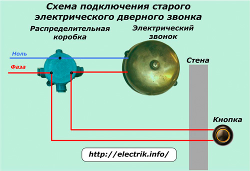
Thus, in the electric bell connection diagram, the junction box connects three cables from each other from:
-
circuit breaker after the meter;
-
buttons
-
call.
The cable connecting the button to the junction box passes through the wall into which the door unit is mounted.
Usually, such a connection scheme is carried out by builders during the construction of the building and is incorporated into the project for the production of works. With self-construction, for the internal hidden laying of wires I will have to ditch the walls.
Sometimes near the place of installation of the bell, a socket is mounted, into which a common zero and the end of the phase wire coming out of the button are inserted. It is not intended for other purposes, since the phase conductor is constantly broken by the contacts of the button.
The current loads generated by the call are small. In addition, they occur for a short time. Therefore, the thermal effect on the wiring is negligible, which allows the use of a reduced wire cross section. Most often, 1.5 mm square is chosen not according to thermal load, but according to indicators of mechanical strength.
Depending on the needs of the residents of the apartment, the typical layout may vary.
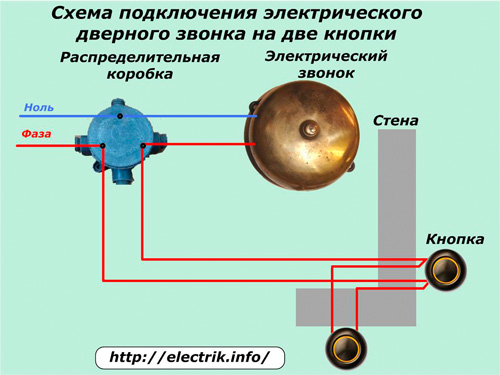
Connecting an electric bell from two buttons
Sometimes when the apartment is located in a common vestibule, which is locked, it becomes necessary to install the bell buttons on the vestibule door and entrance door, so that the guest from the entrance and the apartment neighbor can conveniently call the owner.
In this case, a cable is added to the previous circuit, connecting the button contacts with a parallel connection with its two cores.
When you press any button, the phase enters the call and it rings.
Connecting two electric calls from your buttons
This situation may arise when it becomes necessary to call various people living in the neighboring rooms of the same apartment, for example, for rent.
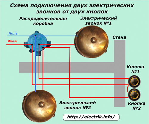
The peculiarity of this scheme is that:
- a three-core cable is laid to the button block from the junction box;
- electric bell number 2 is connected with its own cable.
Here, the phase coming from the junction box is connected to the contacts of both buttons by a jumper, and the outgoing wires are sent to their calls. After assembling the circuit and testing in operation, the buttons are signed, indicating their purpose.
Modern secure doorbell connection
All three circuits considered work in buildings equipped with electrical wiring mounted on TN-C system. In modern conditions, there is a transition to the TN-S or TN-C-S system. They add an additional protective PE conductor, which combines the metal housings of all devices with ground through a junction box.
A variant of the first connection diagram according to this principle is shown in the picture.
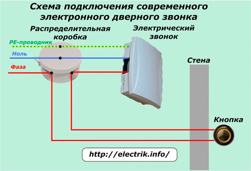
In other circuits, the PE conductor in the same way connects all the housings to the ground loop.
Features of using wired calls
The following examples show the direct connection of equipment to household voltage circuits of 220 volts. However, for safety reasons, this value may be reduced. Even the inclusion of a transformer at least 60 volts in the wiring diagram dramatically reduces the likelihood of a person falling under the influence of current.
Such schemes are used not only in household devices, but in industrial plants with hazardous equipment.
Such designs work on the principle of a radio transmitter and receiver. To transmit / receive a signal, a battery button is installed on the transmitter button and the receiver call.
On some devices, the receiver works without batteries. It is equipped with a plug inserted into the outlet and a built-in power supply. Such models do not work with power outages, but such cases rarely occur.
When the button is pressed, the transmitter emits a radio signal, and the receiver receives it and launches the algorithm for sounding the melody for the time set by the user.
Wireless calls during installation do not need to perform the laborious work of laying cables. Their connection consists in fixing on the wall with fasteners or even with a simple adhesive tape. This is their main advantage.
The disadvantage of such models: the need for periodic replacement of batteries, which are gradually discharged during operation.
See also at bgv.electricianexp.com
:
