Categories: Electrical connection of equipment
Number of views: 24349
Comments on the article: 1
How to connect a boiler to an electric network, boiler connection diagrams
Comfortable living conditions for a modern person provides hot water. In urban conditions, it is centrally supplied by utilities. Residents of rural areas, summer residents, owners of private houses quite often have to deal with this issue on their own.
For them, the industry produces numerous designs of water heating units, which differ in design, performance, operating conditions. Most of them have the name "boiler".
Under this term, it is customary to understand a boiler with a coolant that is heated inside the structure or from its external side.
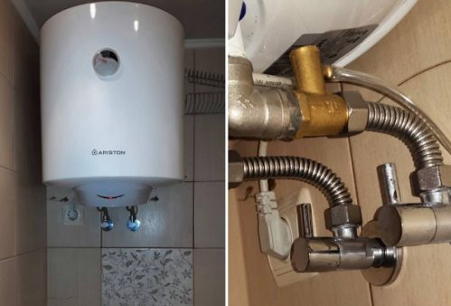
An indirect type boiler operates due to a heating source located outside its body when the temperature is transferred to the heat carrier circulating through the coil built into the inside. Such models require continuous combustion of fuel.
Direct acting boiler uses an internal heat source. For domestic purposes, electrical structures are widely used, working according to one of the principles:
-
resistive heating by heating elements;
-
heating by induction currents.
In both cases, the operation is controlled and the boiler is connected to electric energy according to the same schemes based on the flow of current through the heating element to heat it or turn it off for cooling.
Features of the design of the electric boiler
Inside an hermetically sealed boiler with a coolant - water circulating along hydraulic lines from pipelines and radiators located indoors, an electrical circuit is mounted, including:
-
a water heater, which most often serves as an ordinary resistive heater;
-
coolant temperature meter - a sensor of a special design, the readings of which are processed by a logic circuit to supply voltage to the heater or turn off its power;
-
switching device in bipolar or unipolar design - thermal switch;
-
protective thermal fuse;
-
a heating indication circuit, which can be an ordinary incandescent bulb or an LED with a current-limiting resistor, connected in parallel with the contacts of the heater.
Manufacturers of electrical measuring and switching equipment produce ready-made kits that incorporate temperature sensors, switching devices and a logic unit that provides their mutual connection for regulating the temperature of the coolant.
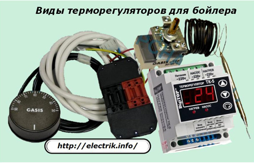
They are called thermostats or thermostats. The temperature sensor is mounted inside the boiler body, and the control unit and switching current contacts are located on the outside.
Thermostats can be performed on an analog base or use microprocessor technology. The constructions of the latter possess:
-
more adjustment options;
-
easy to use settings settings;
-
convenient interface;
-
information board;
-
additional operational functions.
An example is the TK-5 electronic temperature controller with a microcontroller, a display, two temperature sensors mounted at the inlet and outlet of the coolant in the boiler. It allows you to take into account temperature changes within 0 ÷ 120 degrees with an error of 0.5 ° C, which is more than enough for domestic purposes.
The power contacts of the TK-5 thermostat are capable of switching rated currents of 6 amperes.When the heater creates a greater load, the connection of the boiler to the electric network requires modernization - the inclusion of an additional magnetic starter, repeating the operation of the output circuits of the thermostat with high-power contacts.
In some older models of boilers, voltage switching to the heating element can be performed by bimetallic regulators of a mechanical design.
Connection diagram for a boiler through an electrical outlet
Industrial models of small powers up to 1.5 ÷ 2 kilowatts are created, as a rule, for such a connection.
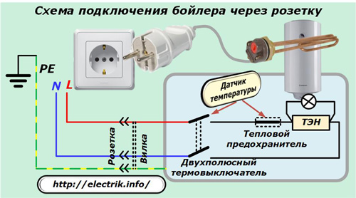
With this method, long-term safe operation is provided by:
-
technical condition of the boiler, which changes during prolonged operation;
-
the correct choice of the design of the outlet according to the load power;
-
taking into account the state of electrical circuits through which voltage is supplied from the apartment panel;
-
the use of protective devices to prevent the consequences of accidental accidents in the circuit.
Features of connecting the boiler to the electrical network via an outlet
The power contacts of the plug-in switching device are designed for a certain type of load, for example, 6, 10 or 16 amperes. Its value is indicated on the body. If the socket is less power, then overheating and destruction of contacts occurs.
For this reason, the boiler must not be connected to a random outlet that does not match its load.
Another requirement for the safe operation of such a circuit is the need for a circuit breaker in it, through which it is possible to break the power supply circuit of the heater under load. The contacts of the socket and plug are not designed to extinguish the electric arc arising in this case.
Wiring Status
The wires of the household network connecting the outlet for the boiler with the apartment shield will fully absorb the load of the heater. They should not overheat. Their material and thickness should be taken into account correctly, otherwise a fire may occur.
To the socket with aluminum wiring, the heater must not be connected, like a copper one, thinner than 2.5 mm square. It is better to use a section of 4 or 6 square. It must first be calculated by heat dissipation and analyzed by installation methods.
Protective devices
The boiler is designed to operate at rated characteristics of the electric network, taking into account the occurrence of random malfunctions in it. To prevent accidents, protection against:
-
increasing pressure in the tank;
-
breakdown of electrical insulation.
If the equipment manufacturer did not provide such protections in the internal structure, then they should be mounted in the apartment panel.
Emergency operation with overpressure inside the boiler
A prerequisite for safety is the presence of a device that prevents boiling of water and the release of dissolved gases from it, because this process creates increased pressure that can break the case.
A similar situation may arise:
-
when the power contacts stick, when they received a command from the temperature sensor through the control unit and are not able to break the electric current through the heater;
-
malfunctions of the temperature sensor, logic unit, or control control circuits.
To prevent such an accident, a second stage of protection is used, configured for a higher temperature setting than for the operating mode. Its value is chosen close to the boiling point, and disconnection is carried out by another, backup contact.
Such an open circuit is called a thermal fuse. The use of a separate temperature sensor for it or the use of an autonomous mechanical structure operating on the principles of bimetallic releases increases the overall reliability of the system.
Emergency mode with leakage currents
The metal casing of the boiler may be under phase potential during breakdown of the insulation of the heater or the connecting wires to the casing.Such a situation is a direct prerequisite for a person receiving electrical injury. It can be fixed by an RCD built into the electrical circuit.
Industrial designs of boilers can be produced with or without a built-in residual current device.
For the correct operation of the RCD it is necessary to ensure a reliable connection of the boiler body to the main grounding bus through the protective PE conductor.
Short circuit of internal circuits
A circuit breaker is designed to disconnect the electrical circuit from the short circuit.
Scheme of connecting the boiler with a cable to the apartment panel
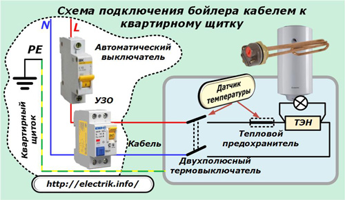
This is the most common option, as usually more than two kilowatts of boiler power is chosen.
Here you must also follow all the recommendations for a secure connection, as in the previous case. A separate cable will be required to the boiler from the apartment shield. It must reliably transmit currents of current loads.
The protection of it and the boiler is organized by a circuit breaker and an RCD or a difavtomat.
Boiler connection diagram taking into account the limitation of allocated power
Any wiring is designed and mounted for specific loads. They are appointed by the electricity supplier. In a modern apartment, the owner of the living space has a large number of electrical appliances. They can easily exceed the power limit that is allocated for them.
Using home wiring in this way is dangerous: it can overheat and create a fire.
To prevent it, you need to turn off powerful consumers when creating critical loads. Given that the heater’s heater is switched on periodically to heat the water, the temperature of which does not quickly decrease, its heating is usually stopped, ensuring the operation of other appliances, such as a refrigerator, washing machine or dishwasher.
For this purpose, an electronic device is used that has the functions of:
-
measuring the current power consumption of the network;
-
comparing its value with the value of the set point to identify the moment of critical overload;
-
disconnecting selected consumers according to a pre-prepared algorithm;
-
automatic renewal of power for decommissioned devices when restoring conditions for their normal operation.
Industrial Development
As such a device, you can use the factory power limiter OM-110.
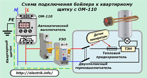
It will prevent frequent power outages by the circuit breaker from overloads, create a normal mode of power consumption for all connected electrical appliances.
OM-110 power limiter is designed to work with loads up to:
-
two;
-
or twenty kilowatts.
For the second operation option, the wire connection diagram is performed as follows.
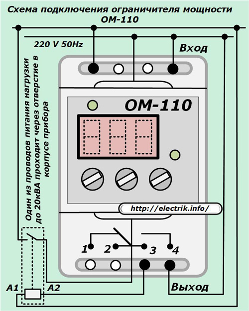
When connected to work with loads up to 20 kVA, one of the supply wires is passed through a housing in which a built-in current transformer is mounted, which is a sensitive measuring body.
DIY homemade power limitation device diagram
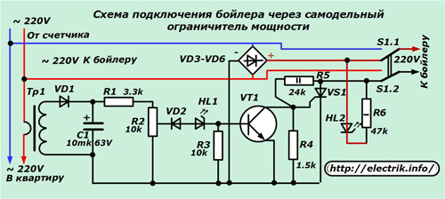
A similar design is able to perform any amateur radio. In it, the phase and zero conductors go directly from the electric meter to the apartment and branch to the boiler. The phase is passed through the primary winding of the measuring transformer, made one and a half turns of a wire that can withstand a load of up to 30 amperes.
The contacts of the manual switch SA1 with thyristor VS1, diode bridge VD3 ÷ 6 and connecting wires are selected for the same value. In this way, a power reserve of the circuit is created, ensuring its normal operation in different situations.
The measuring transformer can be wound on any iron. The primary winding is made of a solid wire or several parallel chains, and the secondary is wound with a monolithic core with the number of turns of about one and a half thousand.
The windings between themselves and the magnetic circuit are separated by cardboard dielectric or fiberglass gaskets.
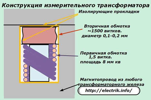
After the secondary winding, a diode VD1 is connected, which in an impulse mode recharges the electrolytic capacitor C1. This chain is configured so that at a current through the primary winding of 30A, a voltage of 45 volts is formed on the capacitor.
It is fed to the control unit of the base of the transistor VT1 through current-limiting, regulating and shunt resistors R1, R2, R3 and an indicator LED HL1.
Potentiometer R2 during commissioning sets the current causing the breakdown voltage of the Zener diode VD2 (taking into account the LED). At this moment, the transistor VT1 opens and the control electrode of the power thyristor VS1 is shunted to the minus of the circuit, from which it was previously separated by the voltage drop across the resistance of the resistor R4. In this case, the thyristor closes and turns off the current passing to the boiler.
It should be noted that the shutdown time does not exceed ten milliseconds, which is two times faster than conventional relay circuits of a mechanical design with a measuring and executive body.
A current will flow through the HL1 LED, and with its glow it will indicate the thyristor is triggering, leading to the shutdown of boiler heating.
The HL2 LED informs about the voltage supply to the heater in its operation. In a working circuit, one of the LEDs is lit. When they are simultaneously extinguished or burn, then this is a clear sign of malfunction. The power limitation circuit must be disabled. To do this, the boiler is transferred to work from the sinusoidal alternating current network into the normal mode with the SA1 switch.
A feature of this development is that it is designed to power only resistive loads, since in it the alternating voltage of the diode bridge is converted to constant. Therefore, such a boiler connection scheme cannot be used to operate devices with asynchronous motors and other devices that need a clean sine wave.
Even incandescent bulbs partially reduce their life under the influence of current ripples. Normally, only an electric kettle, iron, or fireplace with heating elements can work in this circuit.
If the design of the boiler uses electronic rather than bimetallic temperature controllers, then for their power it is necessary to supply voltage corresponding to the factory operating mode.
See also at bgv.electricianexp.com
:

