Categories: Electrical connection of equipment
Number of views: 31793
Comments on the article: 2
How to install and connect a telephone jack
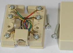 During the development of communications, several standards have been created for connecting stationary telephones to existing lines. Almost all of them are used to some extent in everyday life and in industrial enterprises.
Inside the networks of large organizations that have existed for several decades, you can find simultaneously working models of various designs, mounted at different times. Features of their device must be considered before installing and connecting the telephone.
Purpose and standards of telephone outlets
The main task of the socket is to ensure a quick and reliable connection of telephones to the existing communication lines created by the stationary part - a socket or “mother-contact” and a movable plug inserted into it: “father-contact”.
Design Features
Any electrical outlet for communication systems consists of:
1. Cases-stands made of dielectric materials: plastic or ceramic;
2. spring-loaded metal contacts, ensuring reliable passage of network currents into the telephone through a plug and cord;
3. terminal clamps for connecting wires from a fixed network.
All these devices are classified as low-current circuits. They can be made for installation:
1. hidden in the wall;
2. overhead method.
Installation features affect the types of installation and connection of outlets, which must be taken into account, combined with the design of the telephone sets used.
Features of core standards
For a telephone communication line, before, only two wires were used, creating a closed circuit for the current path, and inside the socket, two contacts were also used to connect them.
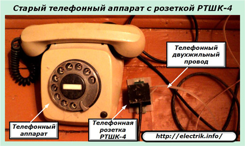
If you cut the plug and socket and twist it or otherwise connect the metal wires of the telephone set wires and the working network in pairs, and then wrap a layer of electrical tape, the connection will work. This principle was used to create an integral connection through a special outlet box.
It works reliably now. Only for its implementation modern designs of contact systems and reliable methods for their isolation from harmful environmental factors are used.
In modern conditions, the integration of low-current circuits, telephone line systems and computer networks. Equipment for them is constantly updated, modified.
Inside low-voltage systems, sockets are installed that are created according to different RJ standards with several pairs of contacts. They have the technical ability to connect a telephone. This is often used by specialists, using only two of the available contacts.
An overview of typical models of detachable joints, their types are given in table No. 1.
Types of Low Current Connector Standards
Table number 1
Connector Differences
RTShK-4 - telephone socket with four contacts for plug connection with a capacitor
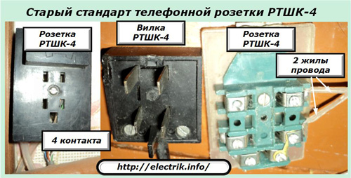
The standard has been working since the eighties. The plastic case of the plug and socket has a dielectric key, eliminating the incorrect connection of the electrical circuit.
When installing several phones on the same line, the corresponding number of RTShK-4 sockets connected in parallel was created. A capacitor with a capacitance of 1 st at 1 microfarad was mounted at the end of the line to conduct technical tests and create “line busy” effects on the side of the calling user.
RJ-11 Connectors
Now telephones, sockets and plugs are equipped with an RJ series connector, which has the same housing, dimensions and design for connecting one, two, three or four pairs of electrical circuits. However, they can be equipped with different designs of plastic locks with special cutouts that exclude the installation of individual RJ11, 14, 25 plugs in RJ45 connectors.
They must be taken into account when connecting various manipulators. Otherwise, you can not get an electrical contact or even break the connector, break its body.
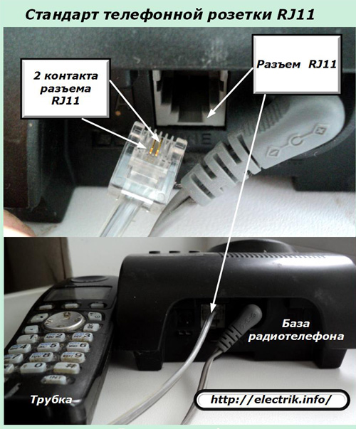
The RJ11 interface is designed exclusively for a two-wire telephone line. It can be used not only for one telephone, but used by several devices assembled in blocks for various devices.
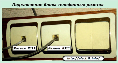
The RJ11 connector is widely used not only in stationary models, but also for connecting the base of radiotelephones that allow you to talk at a certain distance from it due to the technology of radio transmission of signals between the handset and the base through the air through an electronic receiver and transmitter.
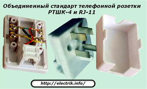
Combined RJ-11 connectors with RTShK-4
The method of connecting telephone sets through combined adapters equipped with combined connectors is implemented in a composite design, which allows simplifying installation with an additional accessory.
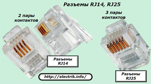
RJ-14, RJ-25 Connectors
Their appearance corresponds to the previous design RJ11. The difference lies in the number of contacts and possible differences in plastic locks.
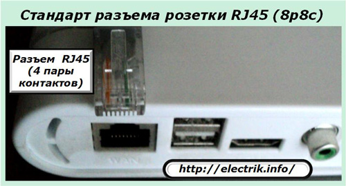
RJ-45 Connectors
They are created for low-current circuits with four pairs of contacts, allowing the use of circuits for connecting complex communications and computer systems used in modems, laptops and other similar devices.
Methods for marking switching circuits
The contacts of the sockets are connected in accordance with a previously developed circuit. The design of the telephone most often allows you to ignore the polarity of the connection. However, for some devices this is technically unacceptable: they may not work correctly or fail.
To facilitate installation and troubleshooting in the circuit, manufacturers mark the contacts. It can be carried out:
1. by putting numbers near the contacts or marking them on the wiring diagram:
2. highlighting wires in a specific color.
In practice, there may be several ways to switch wires. They are shown by tables No. 2, 3, 4.
Marking for connecting twisted pair cable cores to a power outlet
Table number 2
Old marking for connecting cable cores to a power outlet
Table number 3
German marking for connecting cable cores to a power outlet
Table number 4
Connection schemes for telephone outlets and plugs
Let us examine the question on the example of the RTShK-4 connector, used for communication not only with the end subscriber, but also for an additional line - communication between the secretary and the director.
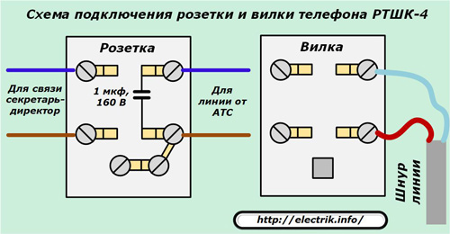
One pair of contacts is activated on the line going from the telephone exchange, and the second - for the organization of additional communication through the service channel.
The diagram shows the installation site of a capacitance of 1 microfarad with an operating voltage of 160 volts. Now they refused such a connection, they stopped mounting the capacitor. This practically does not affect the quality of communication.
The designs of the RTSHK-4 connectors are already outdated. They are gradually being replaced by new, more convenient devices that take up little space. But, the electrical connection diagram has not fundamentally changed. For the operation of one telephone, it is still quite simple to create a closed electrical circuit with a line of automatic telephone exchange of two wires.
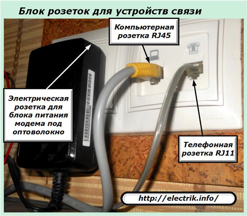
It is customary to combine modern telephone outlets into consolidated units used in combination with other communication devices: computer equipment, fiber optic cable networks, and electrical devices.
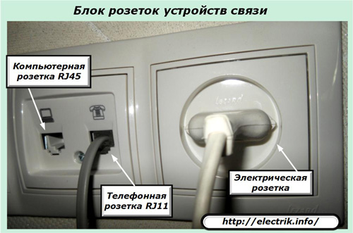
Such blocks are concentrated in one convenient place for maintenance and hidden from prying eyes.
Hazards of the telephone network
No matter what the "experienced" electricians-signalmen, who were "shocked" by the current from the voltage of the automatic telephone exchange line, say, safety issues must be given attention.
Connecting a telephone wall jack is usually done with the line idle. Its value is about 60 volts. If it is possible to catch the moment of an incoming call, then a variable sine wave with an amplitude of up to 120 volts passes through the network.
It may well create a path of current through the body of the master performing the connection. If the hands are wet or sweat has appeared on the body, then the conductivity will increase sharply. Pain sensations will become very unpleasant, cause convulsive reactions. It is better to avoid protecting them with thin dielectric gloves and observing other technical measures of safety rules.
Installation methods for telephone outlets
Taking into account certain technical aspects, telephone sockets are mounted in the same way as ordinary electric sockets. These points are already described in the article: “Features of installation of sockets and switches”. Check it out: preparation and fastening methods for open and closed wiring systems are already disclosed there.
You will also find useful material on this subject in the article. about using plastic cable channels for wiring and low current circuits. This method is used when the repair is completed, dirty work cannot be performed, and telephone wiring must be laid beautifully and neatly.
Modern plastic cable channels can be selected for any room design. They are equipped with numerous accessories, including electrical and telephone outlets.
Thus, in order to install and correctly connect a telephone socket, you need to select its model according to the dimensions and technical characteristics that correspond to your telephone set, and also take into account the recommendations set forth in the proposed material.
See also at bgv.electricianexp.com
:
