Categories: Electrical connection of equipment
Number of views: 58510
Comments on the article: 5
How to connect a voltage regulator to home wiring
The electricity that comes to our apartments is strictly regulated by the legislation of state standards. In accordance with the requirements of the International Electrotechnical Commission for network 220, the deviation of the supply voltage is allowed within ± 10% of the nominal value or from 242 to 198 volts.
Even such a scatter of readings does not always favorably affect the operation of sensitive household electronic devices and ordinary, simple incandescent lamps used in lighting. Electricity distribution companies use transformer substations with power lines that supply electricity to each house and apartment.
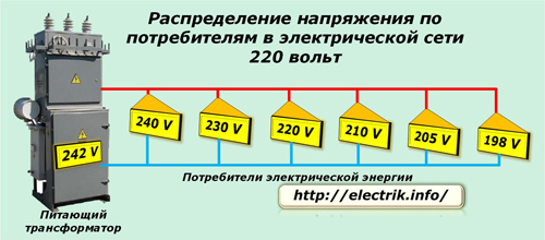
Often, when the lines are loaded, a situation arises when the maximum voltage is already set on the transformer, and only its lower limit reaches the last consumer. If the load increases even more at any facility, then at the end of the line it is no longer possible to maintain regulatory requirements - the power of the transformer substation has been exhausted. The 380 volt network works according to the same principles.
The given case explains the operation mode of electrical installations under ordinary conditions. In fact, the electricity supply to residential buildings, especially in cold winters and in rural areas, can be significantly degraded.
It is possible to correct the current situation with the quality of electricity for each owner of a house or apartment with the help of devices that stabilize the main electrical parameters of the network, which are widely available on sale.
How the voltage regulator works
The principle of its operation is based on the transformation of incoming electrical energy to the optimal value of the output voltage, which will power household devices.
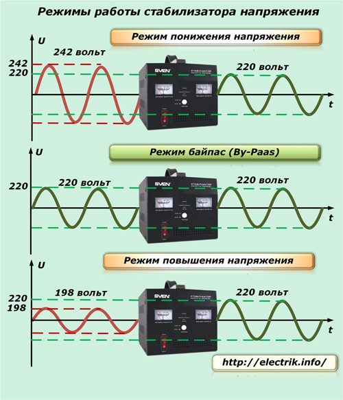
During transformation, the stabilizer can work in one of the following modes:
1. lowering the amplitude;
2. simple transfer;
3. increase the voltage.
In the second case, the transformer simply converts one harmonic to another without changing its amplitude. This consumes energy, which is uselessly spent on heating equipment.
To this end, manufacturers endow certain models with a bypass function by placing a switch on the instrument housing that allows the operator to shut down the entire power part of the equipment from operation. The reverse action turns on the device.
Design Features
Technical characteristics of different voltage stabilizers can vary significantly among themselves in:
-
power transmitted through them;
-
minimum and maximum value of input values;
-
a set of additional features.
This allows a differentiated approach to the choice of a model suitable for the specific conditions of a particular consumer.
Types of voltage stabilizers
By the principle of action, equipment manufacturers produce models combining the transformation of electricity with servo mechanisms, relay control, and the use of semiconductor technologies. You can read about their device and features, recommendations for selection here.
Terminal output
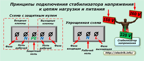
Depending on their purpose and device, stabilizers can have a variety of ways to connect power circuits and loads. The picture shows two common variants of terminal blocks for single-phase models.
In a circuit with a protective zero, the PE conductor is connected to the middle terminal. Working zeros are suitable for adjacent terminals, and phase wires are switched at extreme positions.To connect the input circuits, the left half is used, and the output circuits are mounted on the right side.
This arrangement resembles the algorithm of our writing and reading: from left to right, so it is easy to remember.
For circuits without a protective zero, the terminal strip is simplified: on it, usually the working zero is integrated inside the case, and only three contacts are left to connect the circuits:
-
supply chain phases;
-
total working zero;
-
coming out of the stabilizer phase.
On the simplest and most low-power models, the input circuits can be connected with a cord with a plug, and for connecting consumers, sockets are used directly on the device.
However, the listed laws are not mandatory rules and on each device some specific features can be applied, which the manufacturer stipulates in the technical documentation.
Particular care should be taken when connecting wires when working with three-phase voltage stabilizers.
Seat selection
The output power of the stabilizer determines its size. Small mobile devices can be placed on a table near working electronic equipment. Other, larger structures require stationary installation on the wall, in a niche or on the floor.
A working transformer is heating up. Heat is required to be removed from it. Therefore, it is necessary to position the voltage stabilizer so that all its ventilation openings are free to ensure maximum air exchange inside the housing to remove heat.
Humid air, dust, close proximity to combustible, flammable liquids, elevated temperature negatively affect the performance of all electrical devices. The influence of these harmful factors must be taken into account and avoid the location of the stabilizer in a damp basement, garage, unheated attic.
The choice of location is affected by the length of the cable lines for power supply and load connection. Optimal may be the location of the stabilizer near the input distribution panel in the apartment or house.
Connection schemes for single-phase stabilizers
A rational approach to the electricity supply of the apartment allows you to select from all electricity consumers a group that really needs stabilized parameters. It can be:
-
TV;
-
Office equipment;
-
refrigerator;
-
communication devices.
Household appliances, the main element of which are heating TENs, for example, an electric kettle or the power part of an electric boiler, can not be connected to the stabilizer. They will work without it, but a little faster or slower, which is not particularly critical.
Scheme of connecting one consumer to a voltage regulator
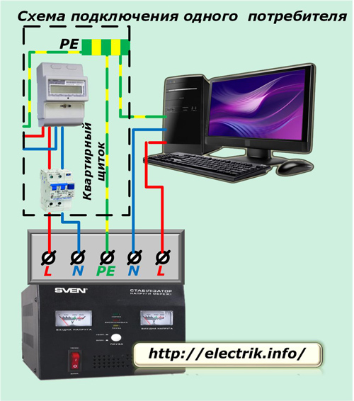
Inside the dashboard after the counter, protection is set in differential automaton (You can use an RCD and a circuit breaker).
From them, the potentials of phase and zero are fed by cable to the input terminals of the stabilizer. The housing of the device is connected to a separate residential bus PE, located in the apartment panel.
The phase and the operating zero from the output terminals of the stabilizer go to the consumer, and the protective zero is supplied to it from the PE bus.
The picture shows a way to connect a computer without indicating connections in an electrical outlet.
Scheme of connecting consumers of the whole house to a voltage regulator
Consider a simplified version when protective earth not used, and to connect the stabilizer used one terminal of the working zero. The number of consumer groups will be conditionally reduced to three.
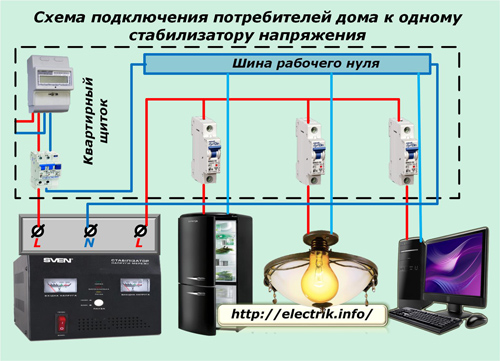
In this case, after the protections, a working zero bus is created in the switchboard. All consumers are powered from it, including a voltage regulator. The phase wire of suitable power from the protection is connected to the input terminal of the stabilizer, and the outgoing cable to the output.Its second end is brought into the shield for parallel connection of the loads.
All consumers distributed in groups are connected via circuit breakers located in the apartment panel.
If the stabilizer uses two terminals for working zero, the circuit will change as follows:
-
the working zero bus will remain connected to consumers, but its connection with protections will be dismantled;
-
the zero wire from the protection of the apartment shield is sent to the input terminal of the working zero of the stabilizer, as is done in the previous diagram.
Connection schemes for three-phase consumers
As a rule, 3-phase stabilizers are block-wise with their own terminal blocks for each block. The switching circuit of their power and load circuits can be performed in various ways.
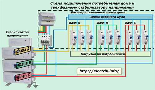
Connecting consumers to a three-phase stabilizer
Here, all those principles that are described in the above schemes are maintained. Only single-phase home consumers should be evenly distributed and connected in groups to different voltage stabilizer blocks to create a symmetrical load on it.
Devices that are powered by a three-phase voltage should be protected from possible accidents in the network with their circuit breakers.
This connection scheme is more suitable for buildings in which powerful three-phase electric motors operate. But, in domestic conditions this is a rather rare case, and a three-phase stabilizer is expensive. If it fails, then all consumers will have to switch to mains power without it.
In everyday life, you can apply another principle of voltage stabilization for connecting electrical appliances of a three-phase network.
Schemes for connecting three-phase consumers through single-phase stabilizers
Household appliances usually consume significantly less power than their industrial counterparts. Therefore, to normalize the network parameters, it is allowed to apply three identical voltage regulators of the corresponding load for a single-phase network.
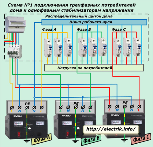
If they use the separation of the working zero, then the scheme No. 1 below is suitable for their connection.
On it, in order to improve the visibility of the information, the bus of the protective PE conductor is not shown, and the connection of the stabilizers to it is shown in a simplified way.
The working zero after the protections located in the distribution panel of the house is bred to the input terminals of each stabilizer. Its bus is formed by parallel connection from the output terminals of all three devices. Working zeros are sent to all consumers by cable cores from this bus.
The input phase terminal of each stabilizer is connected to the corresponding terminal of the protective device, and the output terminal is connected to a group of circuit breakers that supply consumers.
The combination of incoming and outgoing working zeros directly on the stabilizer body at first glance simplifies the scheme, but, for certain models, this technique may disrupt the execution of individual control algorithms, especially when emergency conditions occur. For this reason, manufacturers make such a separation.
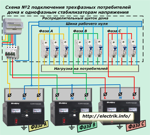
If they do not see any reason to output an additional terminal, then they themselves also simplify the design. Scheme No. 2 for connecting such stabilizers to consumers of a three-phase load is given below.
In conclusion, I want to draw attention to the fact that all the circuits are given in order to familiarize themselves with the principles of operation and the connection of voltage stabilizers. Therefore, they do not have many switching devices, junction boxes, sockets, and other devices necessary for installation and operation.
To create a working circuit, it is necessary to take into account additional specific features of the house wiring, the selected type of stabilizer, and the presence of protective devices.
See also at bgv.electricianexp.com
:

