Categories: Auto electrician
Number of views: 1523
Comments on the article: 1
How electronic speed sensors for cars are arranged and work
Automobile speedometers have not been limited in their operation to mechanics for a long time. Today, electronic speed sensors are used to measure speed, counting electrical pulses using optoelectronic or magnetoresistive circuits. Thus, modern speed sensors are two types of sensors - optoelectronic and cableless (based on a magnetoresistive element).

The mechanical rotation is transmitted to the optoelectronic sensor from the so-called “speedometer cable” coming from the gearbox of the car, and already inside the sensor itself, using the photo-interruption unit, the cable rotation speed is converted into electrical pulses of the corresponding frequency. As for the sensor without a cable, its magnetoresistive element is simply installed in the transmission, so it does not need a cable at all.
So, the optoelectronic sensor is driven by a rotating cable coming from the driven shaft of the gearbox. In the figure you can see the design of such a sensor.
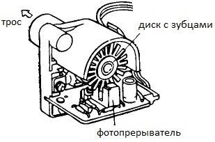
Here, a slotted disk rotating from the drive cable crosses the working area of the photo interrupter, and the electronic circuit then counts pulsed signals, each of which is generated when the next slot of the disk passes through the detector. Obviously, the frequency of the signals is proportional to the speed of rotation of the drive cable.
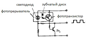
The diagram of the optoelectronic sensor shows that the pulses are removed from the collector of the transistor Tr1, and this transistor will be open when to phototransistor in its base circuit, light from the LED will enter through the slot.
If the slot of the disk leaves its place, and the phototransistor is separated from the LED by a tooth, then the transistor Tr1 will close, although the LED will still emit light. So the valleys and the vertices of the pulses are generated on the collector of the transistor Tr1 - these are the signals that are further counted.
This figure shows the design of the sensor based on the magnetoresistive element.
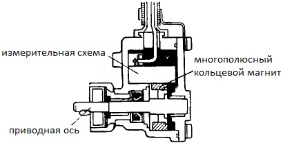
The drive axis of such a sensor is mated to the driven shaft of the gearbox by means of a gear. A multipolar ring magnet is fixed on this axis, which forms during its rotation a magnetic flux changing for a detector at a certain speed.
The changing magnetic flux from a magnet rotating on the axis acts on the measuring circuit, namely on its magnetoresistive element, the resistance of which changes under the influence of a magnetic field.
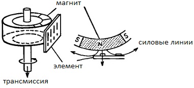
The changing resistance is fixed by the bridge circuit, as a result, 20 pulses are obtained in one revolution. Since the resistive element is designed so that its resistance depends on the external magnetic flux, the following circuit of the element is obtained.
When the magnetic flux penetrating the element at right angles is maximum, the resistance of the resistive element is minimum and the current through it is maximum, and when the direction of the magnetic flux is parallel to the current through the element, the resistance of the resistive element is maximum and the current through it is minimal.
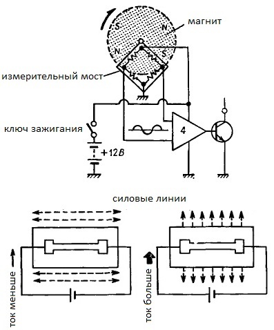
Comparator fixes the difference in voltage drops on the measuring bridge, respectively output transistor it closes and opens with each pole change of a magnet rotating on the axis of the sensor. The signals are removed from the collector of the output transistor, their frequency is then calculated by a digital circuit.
Sensors of both types at a speed of 60 km / h receive 637 revolutions per minute, with 20 pulses per revolution.It is easy to calculate that at a speed of 80 km / h the sensor will have 849.333 revolutions per minute, and accordingly the pulse frequency will be equal to 283.111 Hz. So using a speed sensor and measured the speed of the vehicle.
Car electrical equipment - composition, device and principle of operation
See also at i.electricianexp.com
:
